Let me see. So I am sitting here at the bench, and have an idea for a circuit. Instead of dummying up the circuit with solder right now, I should enter the circuit into board prep, send it to China, and wait for a board to arrive?
Let me see. So I am sitting here at the bench, and have an idea for a circuit. Instead of dummying up the circuit with solder right now, I should enter the circuit into board prep, send it to China, and wait for a board to arrive?
Yes. No excuse. 😀
There has once been a great man saying »Everything should be made as simple as possible, but no simpler.«
And now here we are.
What‘s simpler: PTP (requires technique and imagination, lots of) or first make a board (sorry, german, but: like this: Frag Jan zuerst- Ask Jan first: Roehren und mehr ) which requires imagination and technique, lots of).
And now here we are.
What‘s simpler: PTP (requires technique and imagination, lots of) or first make a board (sorry, german, but: like this: Frag Jan zuerst- Ask Jan first: Roehren und mehr ) which requires imagination and technique, lots of).
Harsh perhaps?
Just remember that this kind of stuff used to be in commercial production...
There is a radio guy on Youtube that I saw a while back who shows some of that 'island' technique (which is mainly for prototyping btw) here: YouTube
I thought it to be quite useful for quick and dirty testing or for quickly constructing test rigs. More sturdy than plastic breadboards anyhow.
Indeed, that "old school" point-to-point wiring was common for the old tube stuff.
BUT...... you have to understand that even though it looks messy, it was solidly constructed with tag strips and anchors to the chassis, AND the layout was thoughtfully laid out for proper reliable operation.
Wires leads were strategicly "dressed" a certain way, components were also dressed for hum reduction, etc.
It wasn't done by a child as some kind of slop mess.
This technology was used in RF techniques especially RF pre amplifiers as they mount in a screened box as a ground plane, to prevent stray capacitance and interference problems.
Looks like it will work but very Heath Robinson!
This seems to make sense, too. But I may get it wrong.
here's a hybrid, somehow:
http://www.waltergiers.de/img/erotischerZyklus.jpg
or a state of the art arrangement:
https://www.analogfan.de/galerie304844.html
Attachments
Given the onset of very cheap Chinse pcb's there is no excuse for that kind of solution now.
KICAD is free and $5 for 5 pcb's is peanuts.
If I could do it myself I'd never send it overboard, ahem, abroad.

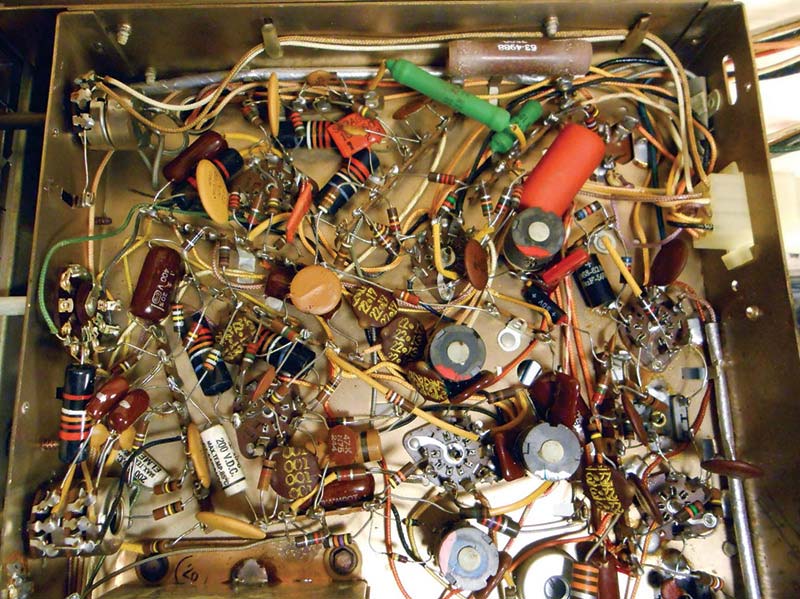
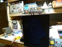
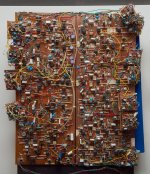
I just stumbled upon a website, qrp-popcorn.blogspot.com, where this image is published. This looks so weird I'm asking myself if this is actually supposed to work? how?
(is this really just a free-floating PTP construction, and all grounding is soldered onto the copperplate while the parts are connected in the air? Is this grounding working?)
The hint you missed is right on the page name 🙂 : QRP
Which means very low power very long distance Amateur RADIO
As in "working (connecting to) all 5 Continents using a 1W transmitter" and similar "impossible" feats.
That type of construction is fine, or even better *recommended* on RF work prototyping.
But ... but ... the 10 for $5 PCBs? ... getting "fluid" to etch your own? ... solderless protoboarding?
I´d like to ask: WHICH PCB? 🙄
An RF, specially very high frequency PCB design is a NIGHTMARE
We are talking designs where a couple inches straight track become transmission lines, where straight angle bends radiate more power than the "official antenna" if you are not very careful, etc.
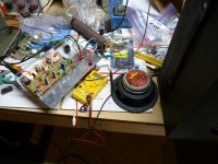
So while prototyping: AVOID the PCB , make part to part connections as short as possible , have a nearby ground plane everywhere, and this type of construction starts making a lot of sense.
As mentioned above, there even is a NASA spec 😱 for this kind of construction.
AFTER you have tweaked your design to satisfaction, THEN you can start designing a PCB.
Which also will need debugging ... lots of it.
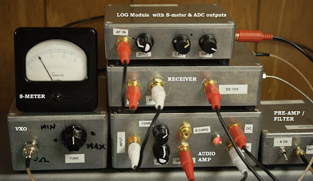
In this particular case, project Author is a solidly RF based guy, who just happened, as a side experiment, to design an Audio Amplifier.
Can you blame him for using a technique with which HE is experienced and comfortable?
But ... but ... what kind of Frequencies is he used to work with?
Well, maybe this snippet from another page where he wonders about ballast Emitter resistors might give you a clue about what´s his normal area of work:
Again: VERY DIFFERENT experience from ours.😀RF Assessment
With a strong RF background, the term 'wire wound resistor' strikes a bit of fear in my heart. I measured my resistor's inductance, plus swept 1 in a tracking generator + spectrum analyzer from ~ 9Khz to 1.3 GHz.😱
Typical inductance of the couple of resistors I tested from my batch= 889 nanoHenries. My sweep revealed that the series resonant frequency (SRF) of 1 of my batch of resistors = ~ 109 MHz. The notch @ ~ 109 MHz isn't very deep; it's around 14 dB down from reference. (clearly very different expectations than ours 😎)
This fits with my lab experiences. I keep a good selection of wire wound chip inductors for building circuits in the 100 - 1200 MHz region😱. Every chip inductor I own has been swept and characterized — I keep a high Q, Coilcraft, wire wound, 880nH, size 0603, SMT inductor and its SRF = 104 MHz. In truth, a chip inductor & a power resistor compare poorly, but give the chip inductor gives a ballpark SRF reference of what to expect.
Of course, the SRF notch of my high Q SMT part is ~44 dB deeper than a lousy 16 Ω power resistor. Since the power resistor is low in resistance (and will go in parallel with other 16 Ω resistors), its a low Q inductor — and with a SRF above 100 MHz, it will work fine as an AF power resistor.
On the contrary, that can be an excellent way to build a prototype, especially if the builder knows what he is doing. For some DIY, every circuit is a prototype.wiseoldtech said:That thing's nothing more than some slop mess.
And anyone constructing such crap shouldn't have access to a soldering iron.
On the contrary, that can be an excellent way to build a prototype, especially if the builder knows what he is doing. For some DIY, every circuit is a prototype.
The advantage of a pcb is very little wiring to do.
Its mostly just soldering in components.
You can also use SMD with a pcb.
Even for a prototype a pcb will at least give a neat reliable base to start with.
Given the project will probably go to pcb later anyway then what you have is a starting point.
With the availabilty of good simulation software you should be close to getting the circuit right anyway.
Simulation works resonably well at Audio frequencies where wiring can be **ignored**
It does not work at all (at least not the kind of simulation we use here) at RF , specially VHF and UHF where every track or wire is an inductor and every two pieces of metal, let alone tracks or wires form a capacitor.
I know RF oscillators and transmitters where tuning comes courtesy of two parallel copper wires/bars and frequency adjustment is made by moving a shorting stub to different points, go figure.
What circuit will you use to draw it?
In a real **prototype** you may start with a basic idea (which you would use to draw that hypotethical first PCB) and then add/pull/modify/rewire so much that you will end with a mess of torn/cut/pulled tracks, wire jumpers all over the place, components piggybacked onto others, etc.
Of course, some call "prototyping" building a circuit pulled from a datasheet, Bob Cordell´s book or Mr Nelson Pass pages and tweak a little capacitor here and there, or try different brands/colours of caps, or plugging different Op Amps in a socket, then go to sleep late at night tired but happy: "hey!!! I have been designing all day long".
Just trhink about two points:
1) there is a reason for Protoboards
2) even more important:
There is a reason for Bob Pease´s "mess" and we all know what came out of all that, HUGE advances instead of the same old refried leftovers.
It does not work at all (at least not the kind of simulation we use here) at RF , specially VHF and UHF where every track or wire is an inductor and every two pieces of metal, let alone tracks or wires form a capacitor.
I know RF oscillators and transmitters where tuning comes courtesy of two parallel copper wires/bars and frequency adjustment is made by moving a shorting stub to different points, go figure.
With due respect, again, WHAT PCB?Even for a prototype a pcb will at least give a neat reliable base to start with.
What circuit will you use to draw it?
In a real **prototype** you may start with a basic idea (which you would use to draw that hypotethical first PCB) and then add/pull/modify/rewire so much that you will end with a mess of torn/cut/pulled tracks, wire jumpers all over the place, components piggybacked onto others, etc.
Of course, some call "prototyping" building a circuit pulled from a datasheet, Bob Cordell´s book or Mr Nelson Pass pages and tweak a little capacitor here and there, or try different brands/colours of caps, or plugging different Op Amps in a socket, then go to sleep late at night tired but happy: "hey!!! I have been designing all day long".
Just trhink about two points:
1) there is a reason for Protoboards
2) even more important:
There is a reason for Bob Pease´s "mess" and we all know what came out of all that, HUGE advances instead of the same old refried leftovers.
Simulation works resonably well at Audio frequencies where wiring can be **ignored**
All my projects are sub 100MHZ so your comments are irrelevant to me.
I also have 40 years design experience so what I draw up for simulation pretty much always works anyway.
I did use prototyping board many years ago but the simulation option and experience killed the need that.
Yes, PCB is neat but almost completely inflexible. None of my projects ever go to PCB, unless you count Veroboard as PCB.nigelwright7557 said:Even for a prototype a pcb will at least give a neat reliable base to start with.
Given the project will probably go to pcb later anyway then what you have is a starting point.
This looks so weird I'm asking myself if this is actually supposed to work?...….. It seems this guy has a better 3-D imagination than soldering-skills.
I see no evidence of poor soldering skills. Yes, it does work as the builder presented teas data on the web page.
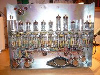
I started out building stuff using tubes, since that was all that was available around 1960. I had zero soldering skills, since I had no soldering iron, or soldering gun.
My first working DIY amp consisted of a couple octal tube sockets screwed to a pine board. In some cases the components that were soldered to the sockets in the TV set that they were cut out of, were left in place and reused, or the wire stub was used for connection. All interconnections were made by wrapping the wires around a brass thumbtack which was pounded into the pine board. It was a guitar amp somewhat similar to an early 1950's vintage Fender Champ, and my parents and neighbors can attest to the fact that it did work.
That thing's nothing more than some slop mess. And anyone constructing such crap shouldn't have access to a soldering iron.....
Somewhere around age 7 or 8 I got a Wen soldering gun for Christmas and the construction technique evolved to soldering the components to the heads of those brass thumbtacks......somewhere in the same time period I discovered Fahnestock Clips.....another giant leap forward.
I actually made some guitar amps with all the parts soldered to the heads of some brass nails that were hammered into a pine board, which was inverted and hung inside the speaker box, looking much like a commercial amp from the outside. I have no pictures or other evidence from the projects of my youth, but I may attempt to recreate one someday just for fun.
When you are learning electronics on your own in the days before the internet, or computers, and your only source of DIY information is the monthly magazines, or the yearly ARRL handbooks, you tend to copy what you see. This kind of prototyping was fairly common in the ham radio world in the 50's and 60's....PC boards were just starting to be seen in consumer electronics and the quality wasn't so good.
On the contrary, that can be an excellent way to build a prototype, especially if the builder knows what he is doing.
There are all sorts of valid prototyping techniques, and this is one of them. It is suited to an analog circuit at audio or sub 100 MHz RF frequency which is a one-off. Some of the great solid state projects from my teenage years looked a lot like this, but far messier.
I made a guitar amp in high school. The preamp was a piece of un-etched PC board that served as the front panel with the pots and switches sticking through it. All the solid state components were soldered to the back using this technique called "sky-wiring." The power amp was a SWTPC Lil Tiger amp board screwed to the inside of the cabinet which also contained a 15 inch speaker liberated from a Hammond organ cabinet.
Sky-wiring is the technique seen in the picture. Dead-bugging usually involved gluing a DIP IC chip (resembling a dead roach) to the PCB material and sky-wiring the components to its legs.
Often these were indeed a first cut experiment just to see if there is a reason to believe that a more serious perf board or PCB version is worth while.
Other times, I may take something that could serve as the basis for a new project, and "sky wire" parts all over it to prove out a concept.
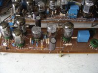
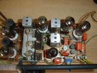
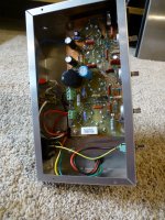
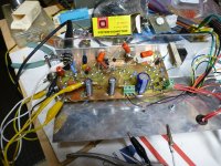
I built a little 4 tube guitar amp for a contest several years back. It worked, but didn't "ROCK." I got it out of the dead projects box after a few years, and proceeded to apply this technique building a "furball" of parts on top of the existing PC board. (picture)
At one point there were clip leads running off to pots for tuning in the operating point of the input tube. Testing was performed with test equipment....and a guitar and several speakers.
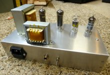
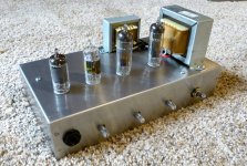
When I was finally happy with the results, I made a new PCB and a better chassis. I still use this amp today. The new version is sitting on top of the cabinet behind the guitar neck. The old "furball" is sitting upside down on top of the RF spectrum analyzer to the right of my ear.
So, this technique worked, and provided the one-off test bed that eventually led to a completed amp project. The original "sky-wired" chassis still exists, because I am thinking about revisiting this design again. Yes, it was a "slop mess," but it provided an opportunity to learn.....and that's what were are supposed to be doing here......working projects are just the side benefit.
Old projects never die, they go into the box of dead projects to be used for parts, or as the basis for something new......that box is pretty big.
Attachments

Fortunately for RF work these days you can simply use microstrip and MWIC's which typically are internally matched to 50 ohms. All the VHF/UHF dead-bug construction is avoidable.
And at microwave frequencies there are a lot of ways to make components directly from the PCB, inductors, capacitors, band-pass filters, couplers - all can be just carefully crafted copper traces. Standard FR4 is rather lossy though, other PCB materials are used.
For instance: Siglent SSA3021X Spectrum Analyser Teardown | Siglent SSA302… | Flickr
That thing's nothing more than some slop mess.
And anyone constructing such crap shouldn't have access to a soldering iron.
This is classic dead bug.
I have seen worse; I used to work with an engineer back in the 80's and it was said that he mounted the parts on the PCB/perf board; loaded up his soldering iron with a big blob and went "flick" at the board and then chiseled away the solder that he didn't need.😱
His stuff was ugly; I rebuilt a lot of it.
Simulation works resonably well at Audio frequencies where wiring can be **ignored**
Irrelevant to you? ... maybe.All my projects are sub 100MHZ so your comments are irrelevant to me.
Irrelevant to the thread? ... not at all.
We are talking a RADIO/Very_High_Frequencies experienced guy who happens to use his tried and true skills when building an prototype.
Emphasis on very high.
You clearly didn´t read what his "average" projects are.
Just to hint at that, these are some of the astounding (for us) projects and areas of interest shown by QRP site owner:
* Teardown & Repair of an Agilent N9020A MXA 10Hz – 8.4GHz Spectrum Analyzer
* Victor Herrero Radio Astronomy Blog
Jupiter events 23 at Juno Waves and other observatories - ----- With many thanks from Victor Herrero-Arrieta to the Teams at Juno Waves, NASA Planetary Data System, STEREO A, WIND, and the Tax Payers
* Jay's Astronomical Observing Blog ... Radio-Sky programs
* Jupiter Modular Receiver Main Index <--- what the title says, it describes a radio astronomy receiver designed to pick RF naturally emitted by Jupiter
yet some self entitled Sound "Guru" Men dare to contest his building skills.
* Radio Astronomy Links
* Solar Ham Data and Graphs
* UHF Bypass and decoupling
* UHF RF Grounding <---THIS
That might mean you don´t really do groundbreaking designs but keep solidly on the old well trodden path.I also have 40 years design experience so what I draw up for simulation pretty much always works anyway.
FWIW after 50 years designing and building Guitar Amps (over 14000 of them by now) I can look at most any Guitar Amp schematic out there and not even need to simulate it to know how it will sound .... so what?
This sort of confirms my guess above.I did use prototyping board many years ago but the simulation option and experience killed the need that.
On the contrary, that can be an excellent way to build a prototype, especially if the builder knows what he is doing. For some DIY, every circuit is a prototype.
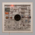
This is a prototype. The builder had some knowledge what he was doing. Dolby SR - Wikipedia
Attachments
- Home
- Design & Build
- Construction Tips
- Is this supposed to work?