The problem is the parameters that cause this problem are not documented in most device data sheets and neither are the PCB layout parasitics that are unique to every amplifier. The damping networks are a general solution shown to work in most cases. If you wanted to calculate the required values, you would have to accurately ascertain all the parasitic elements and the device parameters like Cob, Ccb, base spreader resistance etc. These are not given in audio power output transistors or drivers.Thank you! Great read. I see you also used a 15 Ohm driver emitter resistor. (In the GFA585 circuit, there are also two series 7.5 Ohm resistors connected between the driver emitters.) I still don’t understand what negative effect the additional resistor on the driver base might have.
How can the appropriate resistor value be calculated? Is there a way to do this?
There are several topics about this on the forum, but no concrete answers.
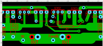
The 30 Ohm resistor was a mistake. In the original circuit, there is no driver base resistor. I first tried 30 Ohms and later reduced it to 10 Ohms. The change was from zero to ten. If I understand correctly, you are suggesting the method shown in the diagram: a parallel RC network on the base. This has no resistance at low frequencies but shows high impedance at high frequencies. (max. 10 Ohm)If you knew the Cib of the driver transistors, you could use T=RC to determine how long it takes to turn the driver off. Cib is not published. What is known, 30 ohm base resistor is 3 times the base resistor of 10 ohms. Shutoff time up to 3 times slower than before. The predriver transistor has to bleed the charge off the base junction of the driver down towards zero to shut off the driver transistor.
Slow turn off can lead to cross conduction of the output transistors. very bad. Only you with physical device and scope can observe whether cross conduction is there or not. Under all temperatures & input signals and loads. If you get cross conduction wrong, you get to buy up to 40 new output transistors. Plus your stage amp dies in the middle of a show somewhere, damaging your band's reputation.
One safe change is to make the 10 ohm driver base resistors inductive wirewound. Like the output resistor the speaker output coil is always wound around. See if that kills your oscillation when you move the predriver-driver wire around.
If not 6 turn inductors are all over the garbage piles of the developed world. Each dead PCAT supply has several. Each dead flat panel TV has more than that. Or make them with 6 turns wire around a AA battery. I know Peavey amps have a 800 uH output coil, and that is 14 turns #16 wire about that diameter. Put inductance series the driver bases, located as close as possible to the driver.
Or buy Self's book to determine what size capacitor goes where.
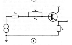
If you set the base stopper too high, you may be creating a pole in the loop response, but that would manifest as loop oscillation at < less than 1MHz.
Personally, I would not agonise over this. The board and the transistors form a complete system at HF and to be able to calculate the values would require you know the parasitic values of the board and the transistors. In an audio power amp you do not have this information unless you have access to a network analyser. The other thing going on here is the device parameters are shifting with applied signal voltages. That’s why I mentioned the damper networks in the bases and collectors and local decoupling are a generalised solution designed to catch this problem and have been developed and refined by practitioners over many years.
Personally, I would not agonise over this. The board and the transistors form a complete system at HF and to be able to calculate the values would require you know the parasitic values of the board and the transistors. In an audio power amp you do not have this information unless you have access to a network analyser. The other thing going on here is the device parameters are shifting with applied signal voltages. That’s why I mentioned the damper networks in the bases and collectors and local decoupling are a generalised solution designed to catch this problem and have been developed and refined by practitioners over many years.
As mentioned by @Bonsai, power decoupling is also important. If you can trigger the oscillation again, try to scope the power rail and the local ground on that board, to see whether you can see the oscillation there.
It's easy to create oscillation. If there is no driver base resistor, oscillation occurs. If there is a 10 Ohm or higher base resistor, there is no oscillation.
If there is oscillation, it is visible at every connection point. I can't pinpoint it.
If there is oscillation, it is visible at every connection point. I can't pinpoint it.
I just thought of something. The driver transistors and the pre-driver transistors operate in Class A. They don’t need to be turned off. Perhaps I can increase the current driving the drivers’ bases. Could this be a solution?If you knew the Cib of the driver transistors, you could use T=RC to determine how long it takes to turn the driver off. Cib is not published. What is known, 30 ohm base resistor is 3 times the base resistor of 10 ohms. Shutoff time up to 3 times slower than before. The predriver transistor has to bleed the charge off the base junction of the driver down towards zero to shut off the driver transistor.
Slow turn off can lead to cross conduction of the output transistors. very bad. Only you with physical device and scope can observe whether cross conduction is there or not. Under all temperatures & input signals and loads. If you get cross conduction wrong, you get to buy up to 40 new output transistors. Plus your stage amp dies in the middle of a show somewhere, damaging your band's reputation.
One safe change is to make the 10 ohm driver base resistors inductive wirewound. Like the output resistor the speaker output coil is always wound around. See if that kills your oscillation when you move the predriver-driver wire around.
If not 6 turn inductors are all over the garbage piles of the developed world. Each dead PCAT supply has several. Each dead flat panel TV has more than that. Or make them with 6 turns wire around a AA battery. I know Peavey amps have a 800 uH output coil, and that is 14 turns #16 wire about that diameter. Put inductance series the driver bases, located as close as possible to the driver.
Or buy Self's book to determine what size capacitor goes where.
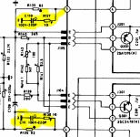
Incorrect. I suggest deleting a low inductance 10 ohm base resistor and replacing it with a high inductance wirewound resistor. Or if that is not good enough, adding a 6 turn inductor series the base resistor. Inductance adds some number to the 10 ohms a resistor has at DC. Impedance of 400 uH at 20 mhz, 48000 ohms. at 1 mhz 2400 ohms. At 20 khz (actual music) 49 ohms.If I understand correctly, you are suggesting the method shown in the diagram: a parallel RC network on the base. This has no resistance at low frequencies but shows high impedance at high frequencies. (max. 10 Ohm)
View attachment 1395755
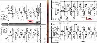
The GFA-565 output board schematic you posted has 10 ohm driver base resistors shown. I hope going from 0 to 10 ohms base resistor you did not edit the adcom schematic diagram.
Last edited:
It’s in the wrong place. And it should be on the driver stage, not the pre-driver and both the resistor and the cap have to be located right at the base of the driver stage and the loop areas kept as small,as possible. The pre-driver has to have its collector supply well decoupled from the driver and OP stage devices as discussed earlier. I can do no more at this stage other than to point you to ‘Designing Audio Power Amplifiers’ by Robert Cordell.
🙂
🙂
I have Cordell's book and Self's book. The RC network of the pre-driver is a factory solution in the GFA565. In later models, the compensation is already on the output board. Take a look at my latest version. I don’t want to make many changes. This circuit is working well now.
In the photo, the output of the two channels.
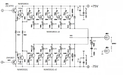
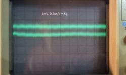
In the photo, the output of the two channels.


Ovidiu (RIP) aka Syn08 did a good job with his OPS analysis. As had already been discussed, the solutions for stabilising an EF3 are pretty much standardised and used by all competent practitioners and you can see that in his final solution.
Let’s also not forget when we read Syn08’s investigation above he had a PhD in electrical engineering ie a seriously capable individual.
Beimler unfortunately does not include the parasitic components in his analysis.
Let’s also not forget when we read Syn08’s investigation above he had a PhD in electrical engineering ie a seriously capable individual.
Beimler unfortunately does not include the parasitic components in his analysis.
Ok. That’s pretty good. If you relay that board out, put the base stoppers for the pre diver right next to the transistors and not on the driver board. Make sure you decouple the OPS well, and you decouple the pre diver right next to it. See the picture of Syn08’s YAP OPS for inspiration. The YAP amp was designed by him and Edmond Stuart (Also RIP) and was the first sub ppm power amp on DIYaudio.I have Cordell's book and Self's book. The RC network of the pre-driver is a factory solution in the GFA565. In later models, the compensation is already on the output board. Take a look at my latest version. I don’t want to make many changes. This circuit is working well now.
In the photo, the output of the two channels.
View attachment 1395961View attachment 1395962
Last edited:
Thank you! I will use the amplifier and observe it. I will make another output board, which will include an output coil (RC network) and the compensation networks for the pre-drivers. I believe that I only had parasitic oscillation problems. The original GFA models are stable and work well. I concluded that the problem was caused by the too-fast transistors (70-100MHz and 30MHz). I didn’t want to make major changes, just enough to ensure stable operation. I will also restore the current of the drivers according to the original design (~125 Ohm and 15 Ohm).
Thank you all for the helpful answers. Many good ideas came to mind during this topic. This is truly a great forum.
Thank you all for the helpful answers. Many good ideas came to mind during this topic. This is truly a great forum.
I’m just posting some forum threads here that are closely related to EF3 issues. This is a great help for the topic.
I'm still at it ... trying for more power , better devices , and keeping it simple and reliable. While reading a little Douglas self (amp handbook), I ran across this statement :
This seemed to deserve more investigation , and the best test was my new triple using njw0281/0302's (drivers) - njw21193/4's (outputs). The 21193/4's have HUGE dies (hefty...
"type 3 is as equally good as type 2 at reverse biasing the output bases, and may give even better HF turnoff as the carriers are "swept" away by a higher resistance connected to a higher voltage" "this remains to be determined..."
This seemed to deserve more investigation , and the best test was my new triple using njw0281/0302's (drivers) - njw21193/4's (outputs). The 21193/4's have HUGE dies (hefty...
- ostripper
- Replies: 121
- Forum: Solid State
- Home
- Amplifiers
- Solid State
- Is this a case of noise or oscillation? How critical is the impact of this signal anomaly
