After a modification to output transistor drive in class AB, it is up to the checkout engineer to prove that cross conduction is not occuring. At all temperatures with all possible signal inputs. SWTC developed a bad reputation because of this problem.Isn't the switchoff capacitor connected to the bases of the output transistors sufficient?
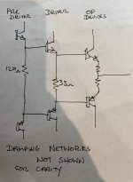
This first picture shows the problem inductances in an EF3. I have not shown the stray capacitances and the device capacitances - those also contibute to the problem.

(The diagram above is detailed in Bob Cordell's book - I've added the power line trace inductances as well).
This is typically how to configure an EF3 to guarantee you don't have parasitic oscillation:-

It is sometimes beneficial to in insert a damper in the pre-driver base - 22-33 Ohms is usually good enough.
The RC damper network in the driver base can be returned to ground or the supply rails - both approaches work well. I usually return them to the supply rails close to a bulk decoupling capacitor. This works of course because to HF AC the rails are a short. It goes without saying the rails around the OPS must be well decoupled with a bulk cap (so 100uF to 220uF although I have used 1000uF x 2 per rail plus 1uF X7R devices (I typically use 2 -3 on each rail).
Note the isolation network in the collector of the pre-driver transistor and the RC decoupling network in the power supply rail between the driver and pre-driver stage. If you have the PSU rail RC decoupling network, you can omit the pre-driver collector RC network.
All base dampers and the collector damper in the pre-driver stage must be placed as close as possible to the transistors. For the OP device dampers, I've settled on 4.7 Ohms 2512 1W SMD devices.
A Zobel is mandatory with an EF3 and must be placed right at the output with very short traces and tight loop areas to be effective. I use 0.1uF and 10 Ohms (non-inductive if I can get it).
See Cordell 'Designing Audio Power Amplifiers' (2011) pages 201-208 for a discussion on the points above.
Here is a snip from a production EF3 amplifier:

Given the fact that you have an assembled unit on a PCB I can guess you do not want to go hacking it, so I'd experiment with the driver base circuit damping network values. Try 15-22 Ohms in the base and then 470-680pF for the cap and initially short out the 10 Ohm resistor and take it from there. If you cannot get it stable, you will have to consider the predriver collector decoupling network.
One other point. I made a serious mistake a few years ago of using a 10k emitter pull-down resistor in the beta helper transistor in the VAS circuit. I had 20-40 MHz oscillation at 20-80mV. I was using an EF2 output stage with all the required dampers, layout considerations, Zobel etc. At the end of the day, the fix was to simply drop the the beta helper pull down resistor to 1k. Problem solved. So, the point here is emitter followers, despite no voltage gain, are very prone to HF oscillation and this is especially the case with modern high fT devices - they like to 'sing' if precautions are not taken.
Finally, I leave you with this - a learning point for me on the use of cascodes (another emitter follower application!):- https://hifisonix.com/technical/cascode-amplifier-oscillation/
(The diagram above is detailed in Bob Cordell's book - I've added the power line trace inductances as well).
This is typically how to configure an EF3 to guarantee you don't have parasitic oscillation:-
It is sometimes beneficial to in insert a damper in the pre-driver base - 22-33 Ohms is usually good enough.
The RC damper network in the driver base can be returned to ground or the supply rails - both approaches work well. I usually return them to the supply rails close to a bulk decoupling capacitor. This works of course because to HF AC the rails are a short. It goes without saying the rails around the OPS must be well decoupled with a bulk cap (so 100uF to 220uF although I have used 1000uF x 2 per rail plus 1uF X7R devices (I typically use 2 -3 on each rail).
Note the isolation network in the collector of the pre-driver transistor and the RC decoupling network in the power supply rail between the driver and pre-driver stage. If you have the PSU rail RC decoupling network, you can omit the pre-driver collector RC network.
All base dampers and the collector damper in the pre-driver stage must be placed as close as possible to the transistors. For the OP device dampers, I've settled on 4.7 Ohms 2512 1W SMD devices.
A Zobel is mandatory with an EF3 and must be placed right at the output with very short traces and tight loop areas to be effective. I use 0.1uF and 10 Ohms (non-inductive if I can get it).
See Cordell 'Designing Audio Power Amplifiers' (2011) pages 201-208 for a discussion on the points above.
Here is a snip from a production EF3 amplifier:
Given the fact that you have an assembled unit on a PCB I can guess you do not want to go hacking it, so I'd experiment with the driver base circuit damping network values. Try 15-22 Ohms in the base and then 470-680pF for the cap and initially short out the 10 Ohm resistor and take it from there. If you cannot get it stable, you will have to consider the predriver collector decoupling network.
One other point. I made a serious mistake a few years ago of using a 10k emitter pull-down resistor in the beta helper transistor in the VAS circuit. I had 20-40 MHz oscillation at 20-80mV. I was using an EF2 output stage with all the required dampers, layout considerations, Zobel etc. At the end of the day, the fix was to simply drop the the beta helper pull down resistor to 1k. Problem solved. So, the point here is emitter followers, despite no voltage gain, are very prone to HF oscillation and this is especially the case with modern high fT devices - they like to 'sing' if precautions are not taken.
Finally, I leave you with this - a learning point for me on the use of cascodes (another emitter follower application!):- https://hifisonix.com/technical/cascode-amplifier-oscillation/
Last edited:
The output circuitry of the GFA-565 and GFA-585 is similar. The transistor types and resistor values are identical. The GFA-565 contains 10 pairs of output transistors. The driver stage operates in class AB and includes a switchoff capacitor in the circuit. The GFA-585 contains 5 pairs of output transistors, the driver stage operates in class A, and there is no switchoff capacitor. I chose the class A driver because it had less oscillation compared to class AB.After a modification to output transistor drive in class AB, it is up to the checkout engineer to prove that cross conduction is not occuring. At all temperatures with all possible signal inputs. SWTC developed a bad reputation because of this problem.
Thank you! I will try these methods.This first picture shows the problem inductances in an EF3. I have not shown the stray capacitances and the device capacitances - those also contibute to the problem.
View attachment 1393782
(The diagram above is detailed in Bob Cordell's book - I've added the power line trace inductances as well).
This is typically how to configure an EF3 to guarantee you don't have parasitic oscillation:-
View attachment 1393783
It is sometimes beneficial to in insert a damper in the pre-driver base - 22-33 Ohms is usually good enough.
The RC damper network in the driver base can be returned to ground or the supply rails - both approaches work well. I usually return them to the supply rails close to a bulk decoupling capacitor. This works of course because to HF AC the rails are a short. It goes without saying the rails around the OPS must be well decoupled with a bulk cap (so 100uF to 220uF although I have used 1000uF x 2 per rail plus 1uF X7R devices (I typically use 2 -3 on each rail).
Note the isolation network in the collector of the pre-driver transistor and the RC decoupling network in the power supply rail between the driver and pre-driver stage. If you have the PSU rail RC decoupling network, you can omit the pre-driver collector RC network.
All base dampers and the collector damper in the pre-driver stage must be placed as close as possible to the transistors. For the OP device dampers, I've settled on 4.7 Ohms 2512 1W SMD devices.
A Zobel is mandatory with an EF3 and must be placed right at the output with very short traces and tight loop areas to be effective. I use 0.1uF and 10 Ohms (non-inductive if I can get it).
See Cordell 'Designing Audio Power Amplifiers' (2011) pages 201-208 for a discussion on the points above.
Here is a snip from a production EF3 amplifier:
View attachment 1393814
Given the fact that you have an assembled unit on a PCB I can guess you do not want to go hacking it, so I'd experiment with the driver base circuit damping network values. Try 15-22 Ohms in the base and then 470-680pF for the cap and initially short out the 10 Ohm resistor and take it from there. If you cannot get it stable, you will have to consider the predriver collector decoupling network.
One other point. I made a serious mistake a few years ago of using a 10k emitter pull-down resistor in the beta helper transistor in the VAS circuit. I had 20-40 MHz oscillation at 20-80mV. I was using an EF2 output stage with all the required dampers, layout considerations, Zobel etc. At the end of the day, the fix was to simply drop the the beta helper pull down resistor to 1k. Problem solved. So, the point here is emitter followers, despite no voltage gain, are very prone to HF oscillation and this is especially the case with modern high fT devices - they like to 'sing' if precautions are not taken.
Finally, I leave you with this - a learning point for me on the use of cascodes (another emitter follower application!):- https://hifisonix.com/technical/cascode-amplifier-oscillation/
Without a driver base resistor, the driver transistor's BC capacitor reduced the oscillation frequency (300pF–1nF). It caused slower oscillations but with greater amplitude. I replaced the 10-Ohm resistor with a 5.1-Ohm one. There was oscillation at startup, but it gradually disappeared.
I installed a 10-Ohm resistor and a 47uF capacitor in the pre-driver's collector, but the problem did not disappear. So far, the most stable solution has been using a 10–30 Ohm resistor connected to the base of the driver transistor.

I installed a 10-Ohm resistor and a 47uF capacitor in the pre-driver's collector, but the problem did not disappear. So far, the most stable solution has been using a 10–30 Ohm resistor connected to the base of the driver transistor.

You do need a series resistor in the base of the driver plus the cap.

1. I don't understand what R301 and R401 are doing - these look like 68 Ohms? To be honest I've never used this and I haven't seen any other EF3 designs with these resistors.
2. The driver transistor emitter tie resistor R302 looks like 7.5 Ohms which means the driver emitter currents are 160 mA (c.f. 1.2V/7.5 ohms) which is extraordinarily high. In most EF3 designs, these are 33 to 68 Ohms and will still keep the driver in class A down to 2 Ohms at the full rail-to-rail output swing - you can always check this in LTspice as well.
3. For the pre-driver emitter tie resistor R314, you can safely set this at 120 to 150 Ohms - 750 Ohms is on the high side.
4. In some cases, a 10-33 ohm vase stopper in the pre-driver collector can also help.
5. Decoupling to the collectors of Q301 and Q402 looks good.


Very strange. I don't think Cordell or Self would do this. All I can suggest is that you configure your OPS in alignment with general practice that has been shown to work. Typically this is a 33 Ohm driver emitter tie resistor
and 120 or 150 ohm emitter tie resistor for the pre-drivers. 15-22 ohms for the driver base stoppers with 470-680 pF cap from the base of the driver to their collectors (you can also take the cap to ground). 4.7 Ohms in the output device bases (10 Ohms is ok - I would not change that). You have decoupled the pre driver collectors, so that's ok.
Can you put the VAS circuit up in a clear way like you did the OPS?
Bonsai is telling you adcom is outside the mainstream of practice.These are the original values in the GFA-565 and GFA-585 circuits.
Another point, NJW0281 NJW0302 are too fast for output transistors. Ft 30 mhz. In PV-1.3k Peavey used fast drivers MJ15020/21 but they used MJ15024/25 for output transistors. Ft 4 mhz. In plastic package MJL21193/94 are 4 mhz Ft.
Last edited:
Let's remove the 750 Ohm resistor. Such an output stage exists. What do you think? But then why is the 750 Ohm included? I don't understand this method either.You do need a series resistor in the base of the driver plus the cap.
View attachment 1394599
1. I don't understand what R301 and R401 are doing - these look like 68 Ohms? To be honest I've never used this and I haven't seen any other EF3 designs with these resistors.
2. The driver transistor emitter tie resistor R302 looks like 7.5 Ohms which means the driver emitter currents are 160 mA (c.f. 1.2V/7.5 ohms) which is extraordinarily high. In most EF3 designs, these are 33 to 68 Ohms and will still keep the driver in class A down to 2 Ohms at the full rail-to-rail output swing - you can always check this in LTspice as well.
3. For the pre-driver emitter tie resistor R314, you can safely set this at 120 to 150 Ohms - 750 Ohms is on the high side.
4. In some cases, a 10-33 ohm vase stopper in the pre-driver collector can also help.
5. Decoupling to the collectors of Q301 and Q402 looks good.

For a Locanthi 'T', you just tie the pre-driver emitters together with a 120-150 ohm resistor, and ditto the driver transistors with 33 ohm. There usually aren't any base-emitter resistors on the drivers - I haven't seen this anywhere else. I'd have to look at this more carefully in a sim, but I suspect the drivers are exiting class A operation quite quickly - in a Locanthi 'T', the pre-drivers and drivers operate in class A up to very high powers into low output loads.
Attachments
Last edited:
This is one of the best picture. At the bottom is the DC servo and the delay circuit.Very strange. I don't think Cordell or Self would do this. All I can suggest is that you configure your OPS in alignment with general practice that has been shown to work. Typically this is a 33 Ohm driver emitter tie resistor
and 120 or 150 ohm emitter tie resistor for the pre-drivers. 15-22 ohms for the driver base stoppers with 470-680 pF cap from the base of the driver to their collectors (you can also take the cap to ground). 4.7 Ohms in the output device bases (10 Ohms is ok - I would not change that). You have decoupled the pre driver collectors, so that's ok.
Can you put the VAS circuit up in a clear way like you did the OPS?

I want to slow down the output to a few MHz due to oscillation. The amplifier limits the input signal to a maximum of 700 kHz. The -3dB bandwidth is a maximum of 80 kHz.Bonsai is telling you adcom is outside the mainstream of practice.
Another point, NJW0281 NJW0302 are too fast for output transistors. Ft 30 mhz. In PV-1.3k Peavey used fast drivers MJ15020/21 but they used MJ15024/25 for output transistors. Ft 4 mhz. In plastic package MJL21193/94 are 4 mhz Ft.

You have a parasitic oscillation problem. Loop oscillation is almost always 1 MHz and usually in the low 100s of kHz range.
Please configure the OPS as I have suggested. This is in line with Self and Cordell and I’ve never had a problem in any of my EF3 designs using this approach. Look at the Honeybadger for further inspiration and validation.
Please configure the OPS as I have suggested. This is in line with Self and Cordell and I’ve never had a problem in any of my EF3 designs using this approach. Look at the Honeybadger for further inspiration and validation.
Just a note: In the GFA-565, the NPN and PNP transistors are mounted on separate PCBs. Perhaps the output design is like this to minimize the wiring between the two boards.

I'll show a better picture. The NPN transistors are on the left side of the amplifier, and the PNP transistors are on the right side. (This is a monoblock.) There is a large distance between the boards. I just realized this. The driver also operated in Class AB. This way, only a few wires were needed between the boards. Now I understand why it’s not a classic EF3 layout.
In my amplifier, there will be only one output board.


In my amplifier, there will be only one output board.
Last edited:
I modified the circuit according to the diagram. It is now a typical EF3 layout. I removed the driver base resistor. I removed the pre-driver collector resistor. Currently, there is an initial 20 MHz oscillation with an amplitude of 100 mV. If there is a 10 Ohm resistor on the driver base, the oscillation disappears.You have a parasitic oscillation problem. Loop oscillation is almost always 1 MHz and usually in the low 100s of kHz range.
Please configure the OPS as I have suggested. This is in line with Self and Cordell and I’ve never had a problem in any of my EF3 designs using this approach. Look at the Honeybadger for further inspiration and validation.

The GFA-565 is finicky about the transistors used in the triple-darlington output stage. For example, it will oscillate if one installs MJE15032/33 in place of the faster and lower cob, original 2SC3907/2SA1516. This oscillation is cured by installing NJW3281/3201 in the second-stage. This combo work fine, but might be inferior to the faster, original setup of 2SA1306/2SC3298 first stage and 2SC3907/2SA1516 second. I'd keep them if they are not blown.
Did the 2SC4793 come with the amp?
Did the 2SC4793 come with the amp?
Hello Phloodpants! You know these amplifiers well. This rebuild contains no TO-3 types. I designed the driver board based on the original 565. I used components according to the EBFA design. I also made a new output board. I searched for faster transistors with low COB. That's why I chose 2SC4793 and NJW0281.
- Home
- Amplifiers
- Solid State
- Is this a case of noise or oscillation? How critical is the impact of this signal anomaly