I have never had a transformer/diode rectifier/ecap power supply oscillate. You could disconnect the input boards from the PS and see if the 20 mhz is still on PS C001 C002.
Did you correct the error in post #11? CE 47 pf cap instead of CB 47 pf cap on Q110/111?
Did you correct the error in post #11? CE 47 pf cap instead of CB 47 pf cap on Q110/111?
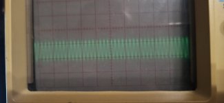
The power supply unloaded signal is 1/4 the frequency of the oscillation on the output. Not the same. Possibly picking up some RF noise in your workroom.
What you can try is to connect the ground clip to the end of the probe tip and then slowly move the loop over the amp board. You may then get a signal peak over the area where the oscillation is arising.
These kinds of problems can be quite difficult to weed out.
These kinds of problems can be quite difficult to weed out.
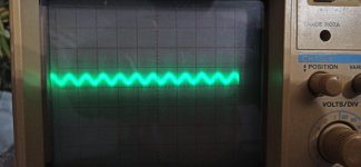
The cause of the high-frequency oscillation was the triple Darlington output stage. In the original circuit, the driver transistor has no base resistor. The pre-driver has 82 Ohms, and the output transistors have 10 Ohms. I added a 30-Ohm resistor to the driver transistor's base. This reduced the oscillation to approximately 1.2 MHz, which is a smaller issue. (2 mV/1 μs/div, x1). Is 30 Ohms an appropriate value?
Attachments

There must be zero HF oscillation. Typically in an EF3 you would have an RC network in the driver base ( I use 15 ohms and 470pF NP0/COG 250 V usually) and a 3.3 to 10 ohm resistor in the base of each output transistor as close as physically possible to the transistor. In the collector of the pre-driver, you have a 15 - 22 ohm resistor and then run a 1 to 4.7 if cap to ground. An X7R works well here. Layout is important since you have to keep trace inductances low and you do that primarily by keeping loop areas small and the overall layout compact.
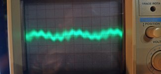
Regarding the PSU HF you picked up: the problem with HF oscillation is it gets into everying no matter where you probe and that’s what makes it difficult to nail down. But, my guess is it’s in the VAS or output stage.
See Robert Cordell’s ‘Designing Audio Power Amplifiers’ for some good advice in this regard.
The pre-driver has a compensation capacitor on the driver board. The remaining oscillation might also be due to the amplifier not being enclosed in a metal case. (?) I will examine it later.

oscilation will not be caused by the lack of a case.
I have had oscilation caused by PSU or interconnect wires being too long. Also make sure the wires from the vas stage to the output stage are as short as possible.
Also make sure the psu and signal wires arent twisted together, this could cause some unwanted capacitance.
If you increase the base resistors, you slow down the output stage, so the miller caps in the vas might need to be bigger. Oh i now see there are no miller caps sorry.
Rather than choosing a larger R in the zobel, try a smaller vallue.
Hope some of this might help!
I use RF Explorer spectrum analyzer and near field antennas to check the amplifier oscillation.
https://j3.rf-explorer.com/menu-models.html
https://www.aliexpress.com/item/100....order_list.order_list_main.32.199f1802LMfycY
https://j3.rf-explorer.com/menu-models.html
https://www.aliexpress.com/item/100....order_list.order_list_main.32.199f1802LMfycY


Much better. Did you prove by scoping that the oscillation is not coming from Q110 Q111? Pin 6 & 3 of the driver board, which have their own zobel. R137 C110, C113 This arrangement is different between the GFA565 schematic and the EBFA565 schematic. Which do you have? The GFA565 has a zobel on pin 6 and the EBFA565 does not.
I copied the original GFA-565 driver board. I designed the output board myself because I am not using TO-3 transistors. The GFA-565 has a Zobel on the driver board (pin 6). The EBFA-565 has the Zobel on the output board. I also placed the Zobel on my output board. Pins 3 and 4 have compensation for the pre-driver transistors.
Well having a zobel on the base drivers coming out of the driver board is weird. Peavey PV-1.3k has no such thing and mine does not oscillate. Maybe because the layout is better. There is a ground wire in the flat cable between the base drive line and the feedback line. Peavey 1.3k has 0.22 uf parallel 100 ohms between the bases of the pnp and npn output transistors. Having zobels on the output transistor drive indicates to me adcom had problems with RF oscillation.
Crown MA1200 has a RLC network between predriver collector and driver transistor base. 4.7 nf parallel 470 uH parallel 75 ohms. They wouldn't spend that much money if they hadn't had a problem.
As rupopulles said, increasing resistance to the bases of the drivers increases the chance for cross conduction in the output transistors. Which can eventually burn them up. Designer beware. Your copy probably does not exaclly copy the wiring and layout of the original, unless you have one to look at.
Nearly all the 'older' types' Crown 'Grounded Bridge and D series have this RLC network between pre driver and driver. I think it is an three emitter follower design or 'triple darlington' as Crown called it. The last outputs are biased in a Class B. At low power they are actually not conducting signal so the pre drivers and drivers only are delivering the signal to load.
Excuse me, I believe there is some misunderstanding. I am attaching the schematic for the output stage circuit.Well having a zobel on the base drivers coming out of the driver board is weird. Peavey PV-1.3k has no such thing and mine does not oscillate. Maybe because the layout is better. There is a ground wire in the flat cable between the base drive line and the feedback line. Peavey 1.3k has 0.22 uf parallel 100 ohms between the bases of the pnp and npn output transistors. Having zobels on the output transistor drive indicates to me adcom had problems with RF oscillation.
Crown MA1200 has a RLC network between predriver collector and driver transistor base. 4.7 nf parallel 470 uH parallel 75 ohms. They wouldn't spend that much money if they hadn't had a problem.
As rupopulles said, increasing resistance to the bases of the drivers increases the chance for cross conduction in the output transistors. Which can eventually burn them up. Designer beware. Your copy probably does not exaclly copy the wiring and layout of the original, unless you have one to look at.
"increasing resistance to the bases of the drivers increases the chance for cross conduction in the output transistors"- Could you explain this? Higher bias current?

The pre-driver collectors are not decoupled as I mentioned earlier. I don’t think this is a good idea.
You could in the meantime try playing either the values of the driver base RC network. Try increasing the capacitance by 100-200 pF. On my original Ovation 250 power amp I used 22 ohms and 1nf which was probably on the high side (but the ULGF was very low as I was using MJ21193/4 devices).
You could in the meantime try playing either the values of the driver base RC network. Try increasing the capacitance by 100-200 pF. On my original Ovation 250 power amp I used 22 ohms and 1nf which was probably on the high side (but the ULGF was very low as I was using MJ21193/4 devices).
The predriver has to discharge the input capacitance of the driver transistors to shut them off. Increasing resistance to the base by 3:1 increases the time it takes to discharge that capacitance. If both PNP and NPN output transistors are on at the same time, more than the 20 ma idle bias current flows and massive heating occurs. Cob of a 2SC2238 used as PV-1.3k as driver (TO-220) is 25 pf."increasing resistance to the bases of the drivers increases the chance for cross conduction in the output transistors"- Could you explain this? Higher bias current?
I understand the RC network (in the picture). But where is the collector decoupling?The pre-driver collectors are not decoupled as I mentioned earlier. I don’t think this is a good idea.
You could in the meantime try playing either the values of the driver base RC network. Try increasing the capacitance by 100-200 pF. On my original Ovation 250 power amp I used 22 ohms and 1nf which was probably on the high side (but the ULGF was very low as I was using MJ21193/4 devices).

indianajo:
Isn't the switchoff capacitor connected to the bases of the output transistors sufficient?- Home
- Amplifiers
- Solid State
- Is this a case of noise or oscillation? How critical is the impact of this signal anomaly