Nelson Pass said:As I think about it more, I would be inclined to think of
the SPLIF as a local feedback amplifier. The dummy
output stage and load mimic the actions of quite a
few other local feedback designs.
Nelson, are you thinking about a specific (Pass Labs) design?
Jan Didden
janneman said:
Nelson, are you thinking about a specific (Pass Labs) design?
Jan Didden
I think Nelson is thinking about his Treshold Stasis amplifiers. These take the feedback from the bases of the driver transistors (emitter followers). So there is not so much difference between the Stasis feedback and the Splif feedback. Splif uses an emitterfollower to drive the feedback, but since the load of that emitterfollower is only little and only resistive, one could as well take the feedback from the bases.
If I remember correctly, Nelson said in one of his posts that this feedback take-off point was chosen for subjective reasons and to call the amplifier overall feedback free, since the feedback is not coming from the output now.
I've not reread this complete thread, so I'm not sure whether Graham Maynard's articles in the last issues of EW have been mentioned. I think these are relevant to the Splif concept. Graham shows how loudspeaker EMF causes disturbances in the feedback loop. This is fairly well avoided by taking the feedback from the bases (of the drivers) of the output transistors. The additional emitter followers in the Splif concept that drive the feedback do not change that, so are equally effective. Of course additional distortion is generated by not incorporating the output transistors in the feedback loop, but on the other hand this additional distortion may very well be less annoying than the distortion generated by current injection (caused by speaker EMF) into the amplifier output.
I think listening to the Splif concept is more interesting than criticizing it just from theory. The distortion effects that Graham Maynard found are also not recognized normally in feedback amplifier design.
Steven
Attachments

Hi, Charles,
What I mean is like what Janneman write
Will Splif works in this "light-load" dummy?
Hi, Steven,
In the Statis sch you attached, a slight modification around Q15-Q16 will make it Hawksford EC (Who has draw it first, NP or Hawksford?)
What I mean is like what Janneman write
If the feedback voltage divider has DC blocking cap, we should remove it to make a full resistive fb voltage divider network.with a light load, possibly only loaded by the fb network.
Will Splif works in this "light-load" dummy?
Hi, Steven,
In the Statis sch you attached, a slight modification around Q15-Q16 will make it Hawksford EC (Who has draw it first, NP or Hawksford?)
lumanauw said:
Hi, Steven,
In the Statis sch you attached, a slight modification around Q15-Q16 will make it Hawksford EC (Who has draw it first, NP or Hawksford?)
Hi Lumanauw,
The schematic of the Treshold shows a date 1984, the Hawksford error correction was presented during the London AES Convention in 1980.
But this doesn't tell a thing. The circuits are completely different and serve a different purpose. The Treshold biasing circuit is a biasing circuit and not an error correction amplifier, although both use 2 transistors. 😀
The Treshold biasing circuit is almost a normal bias arrangement with two transistors acting as Vbe multiplier (Q15/16). The only different thing is that the resistors R17 and R19 are not connected to the bases of Q17 and Q18 as normal, but are connected to the emitters of these emitter followers. Operation is the same.
Steven
Hi, Steven,
There are 2 things that I dont understand about this sch. If P1 is for setting bias, why it is outside VBE multiplier? Just depending on voltage drop?
The second, why Q9 is feeding Q8's base? Whats the purpose of this configuration?
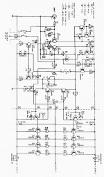
Threshold amps are unique. How about this one, does the VBE multiplier does Error Correction too?http://www.passlabs.com/np/400a-4000.tif
There are 2 things that I dont understand about this sch. If P1 is for setting bias, why it is outside VBE multiplier? Just depending on voltage drop?
The second, why Q9 is feeding Q8's base? Whats the purpose of this configuration?
Threshold amps are unique. How about this one, does the VBE multiplier does Error Correction too?http://www.passlabs.com/np/400a-4000.tif
lumanauw said:Hi, Charles,
What I mean is like what Janneman write
If the feedback voltage divider has DC blocking cap, we should remove it to make a full resistive fb voltage divider network.
Will Splif works in this "light-load" dummy?
Hi lumanauw,
it will work in principle, but a quasi unloaded output stage will be driven in a weaker way, since with such a small load the output voltage (that is dictated by feedback) is reached with a small base- respectively gate-drive; and this small drive may be not sufficient for the speaker output pair, and could result in a kind of current starving distortion (also depending on component matching and bias), that otherwise - with a loaded dummy output - stage would be entirely prevented.
Charles 🙂
hummhoom said:If the quality of you amplifier depends on how accurately the load represented by the speaker is duplicated, why not just use the real speaker? I think that's the idea behind feedback.
I have never said that the dummy load is meant to accurately represent the speaker load. Jan keeps telling that it is meant for that, but it isn't.
On the contrary:
The dummy load is well known to be NOT REPRESENTING the speaker load at all.
The dummy load is a linear pure resistance load, just to give a linear load to the dummy output stage, in order to give the SAME LINEAR DRIVE to the speaker output stage. That's part of the basic idea.
Drawing feedback from the output is not going to amplify the feedback. It's going to amplify the difference between the input(what the output should be), and the output (what it actually is.) If I'm not mistaken, amplifiers evolved to feeback designs to cure defficiencies with non-feedback designs. Why would anybody want to use many many more components to make a more poor quality amplifier?
Well, you can (quite easily) make very very good sounding amplifiers without feedback, using triode tubes. Its just much more expensive and also limited in power.
If you want to make a transistor amplifier without feedback the thing will most likely turn out ugly, as the transistor's inherent sound quality is... well... not so good 😉
So with transistors I would say, you are bound to use a feedback circuit technique, at best global feedback over the entire amplifier, just to correct for the - not so good - inherent sound quality of a transistor.
The SPLIF amp incorporates a global feedback over the complete amplifier, while taking zero feedback from the speaker.
This way it eliminates the harsh harmonic transistor distortion as it uses global feedback, while providing the musical flow of a no-feedback tube-amplifier at the same time. And this concept is scalable in terms of power, which I consider to be novel to no-speaker-feedback amplifiers.
Charles 🙂
Charles said:
....as the transistor's inherent sound quality is... well... not so good 😉
......
....while providing the musical flow of a no-feedback tube-amplifier ......
Charles 🙂
(?)

Enough for me.
Rodolfo
Steven said:[snip]Splif uses an emitterfollower to drive the feedback, but since the load of that emitterfollower is only little and only resistive, one could as well take the feedback from the bases.[snip]Steven
Hi Steven,
I hear you, but don't you think that by including an 'output stage-like emitter-follower' in the feedback loop as in the splif corrects the real output stage to a certain extend? For example, the factor 2 change in Gm when the amp changes from class A into class (A)B will then also happen in the dummy stage and be corrected by the fb loop. So in this respect it would have more feedback-correction then just taking the fb from the drivers.
Which brings then on the question of how to size the dummy load. Elsewhere Charles says it is not supposed to be emulating the speaker load, but then what should it be? I suggested to take a small signal dummy stage with light load which would still have comparable forward non-linearity as the real stage, so still being corrected, but be much cheaper.
[snip]I've not reread this complete thread, so I'm not sure whether Graham Maynard's articles in the last issues of EW have been mentioned. I think these are relevant to the Splif concept. Graham shows how loudspeaker EMF causes disturbances in the feedback loop. This is fairly well avoided by taking the feedback from the bases (of the drivers) of the output transistors.[snip]
I know Grahams articles, but there is quite some ctiticism on the premise of his arguments for 1st cycle distortion as this involves unrealistic signals that will neven be encountered in real music. He uses a signal that starts with an (theoretically) infinitely fast edge. That will surely get any amp into all sorts of trouble, but is irrelevant for practical music reproduction.
Jan Didden
lumanauw said:Hi, Steven,
There are 2 things that I dont understand about this sch. If P1 is for setting bias, why it is outside VBE multiplier? Just depending on voltage drop?
The second, why Q9 is feeding Q8's base? Whats the purpose of this configuration?
Threshold amps are unique. How about this one, does the VBE multiplier does Error Correction too?http://www.passlabs.com/np/400a-4000.tif
You have a good point with P1. Actually, I don't know. I would have expected that R18 was the variable resistor.
I don't think that Q9 is normally driving the base of Q8. I cannot read the resistor values so I'm not sure about DC levels, but I expect that Q9 is only a current limiter for Q8. If the voltage drop over R16 is more than 0.6V Q9 starts to take away base current of Q8.
In the Treshold 400A and 4000 the Vbe multiplier does not do error correction either. As far as I see at this moment the special arrangement with the four transistors around the bias potentiometer is for variable biasing (sliding bias).
Steven
Charles said:
Hi lumanauw,
it will work in principle, but a quasi unloaded output stage will be driven in a weaker way, since with such a small load the output voltage (that is dictated by feedback) is reached with a small base- respectively gate-drive; and this small drive may be not sufficient for the speaker output pair, and could result in a kind of current starving distortion (also depending on component matching and bias), that otherwise - with a loaded dummy output - stage would be entirely prevented.
Charles 🙂
Charles,
It is your amplifier, but I think the Splif principle is better served by having a small or even no load at all at the dummy output stage. This to make sure that the dummy stage remains in class A operation. Because of phase differences between the resistive load on the dummy and the reactive load on the real output it makes no sense to try to get more drive voltage for the positive output transistor just because the dummy transistor requires more drive at that moment.
Furthermore, I don't think there is an issue with current starving of the output transistors. You just have a fixed bias voltage for the output stage and when the positive output transistor is sourcing current to the output, the negative output transistor becomes increasingly more under- or even reverse-biased (mostly dependent on value of emitter resistors and output current). But the positive one will just deliver the required current.
Why not let the feedback take-off point be halfway between the bias voltage? That is what happens with an unloaded dummy stage.
Steven
janneman said:
Hi Steven,
I hear you, but don't you think that by including an 'output stage-like emitter-follower' in the feedback loop as in the splif corrects the real output stage to a certain extend? For example, the factor 2 change in Gm when the amp changes from class A into class (A)B will then also happen in the dummy stage and be corrected by the fb loop. So in this respect it would have more feedback-correction then just taking the fb from the drivers.
Which brings then on the question of how to size the dummy load. Elsewhere Charles says it is not supposed to be emulating the speaker load, but then what should it be? I suggested to take a small signal dummy stage with light load which would still have comparable forward non-linearity as the real stage, so still being corrected, but be much cheaper.
I know Grahams articles, but there is quite some ctiticism on the premise of his arguments for 1st cycle distortion as this involves unrealistic signals that will neven be encountered in real music. He uses a signal that starts with an (theoretically) infinitely fast edge. That will surely get any amp into all sorts of trouble, but is irrelevant for practical music reproduction.
Jan Didden
Hi Jan,
No I don't expect the dummy output stage to correct the real output stage to any extent. I think it is better not to load the dummy stage and keep it in class A. Any correction for Gm-doubling of the dummy stage would not correct the behaviour of the output stage, because it will be mostly at the wrong moment due to current phase differences.
I agree with you that in case of no load at the dummy stage the feedback could have been derived from the bases of the output transistors (or its drivers) more cheaply. I have always thought that the Splif was mainly intended for existing conventional amplifiers with multiple output transistors, where it can be applied by just cutting one PCB track. In case a new amplifier is being developed I would not add a dummy stage just for the sake of creating a feedback take-off point.
True, infinitely steep edges will not occur in real music, but the principle remains the same for real signals although its effect will be smaller. I don't have Graham's articles at hand now, but I think he used also simple sinewaves that just started at t=0. This sudden edge will cause a lot of high harmonics, but is not infinitely sharp (i.e. dV/dt is not infinite).
Steven
Steven said:[snip] I don't have Graham's articles at hand now, but I think he used also simple sinewaves that just started at t=0. This sudden edge will cause a lot of high harmonics, but is not infinitely sharp (i.e. dV/dt is not infinite).
Steven
Yes I think you are right about that, but then again, in the simulator, on which he bases most of his research, the sudden start IS unrealistically steep, no? I remember that at some point in the series someone suggested to run the input signal through a simple RC low-pass of 100kHz or so to get down to *reasonable* real signals, which was vehemently opposed by Graham on the grounds that 'nobody listens to filters' (??) or words to that effect.
Jan Didden
Hi Jan,
Yes, I agree. A sudden start is not realistic. I haven't checked what the effect would be if the signal had been filtered. Actually, I haven't checked anything at all, I only read his story. Exept for his awfully long sentences of half a column of text (many required reading two or three times), I found the stories interesting.
Steven
Steven said:Charles,
It is your amplifier, but I think the Splif principle is better served by having a small or even no load at all at the dummy output stage. This to make sure that the dummy stage remains in class A operation. Because of phase differences between the resistive load on the dummy and the reactive load on the real output it makes no sense to try to get more drive voltage for the positive output transistor just because the dummy transistor requires more drive at that moment.
Hi Steven,,
thanks for your comments.
Hm, when I tried it, I found out, that it sounded better with dummy load, and that different loads change the sound. Therefore I included that rotary switch provision to find the best sounding setting for the connected speaker and application.
Without load, the sound was a little on the thin side, just as if there was no drive. That's how it was with my SPLIF version. But as I understand, some have tried without load and got very good results. So I see it as an option to try out.
Furthermore, I don't think there is an issue with current starving of the output transistors. You just have a fixed bias voltage for the output stage and when the positive output transistor is sourcing current to the output, the negative output transistor becomes increasingly more under- or even reverse-biased (mostly dependent on value of emitter resistors and output current). But the positive one will just deliver the required current.
Okay, my SPLIF prototype has MOSFET output transistors. So there's not a relatively fixed Vbe, but a variable resistance and Vgd voltage. Not loading the output stage, means that the internal resistance of the output MOSFETs will be quite high, since the feedback point does not require any current, and therefore there will only be a weak drive, causing the slightly thin sound that I experienced.
Why not let the feedback take-off point be halfway between the bias voltage? That is what happens with an unloaded dummy stage.
Well, I think, not exactly. With bipolar output transistors it is meant to be the same, BUT then...
... Do different types, brands of bipolar output transistors sound exactly the same ?
Who ever did some listening tests, taking feedback from the VAS, knows that every type, brand, circuit connection and bias current setting of output transistors sounds different.
If there is no global feedback including the 'original' output pair (as in the SPLIFs dummy stage) those effects aren't corrected by feedback, which means increased distortion (as obvious on those amplifiers that take feedback from VAS).
Therefore, I also think that a smaller (cheaper) dummy output stage will basically work, but lead to non-optimum results.
The SPLIF does not try to mimic the speaker load, but it tries to mimic the output stage-nonlinearities, and those are covered by global dummy fb.
Charles 🙂
Charles said:
I have never said that the dummy load is meant to accurately represent the speaker load. Jan keeps telling that it is meant for that, but it isn't.
On the contrary:
The dummy load is well known to be NOT REPRESENTING the speaker load at all.
The dummy load is a linear pure resistance load, just to give a linear load to the dummy output stage, in order to give the SAME LINEAR DRIVE to the speaker output stage. That's part of the basic idea.
You specifically DON'T want a linear drive to the output stage. Well you do, by having a linear output stage, but what you REALLY want a linear output AFTER the output stage. Well, where you REALLY REALLY want the linear response is at the speaker cone I guess. You want the voltage to translate into a velocity of the cone to translate into displacement of air to translate in compression and rarefaction of the air.
Charles said:
Well, you can (quite easily) make very very good sounding amplifiers without feedback, using triode tubes. Its just much more expensive and also limited in power.
If you want to make a transistor amplifier without feedback the thing will most likely turn out ugly, as the transistor's inherent sound quality is... well... not so good 😉
There are as many harsh tube designs, both feedback an none, as there are silicon designs my friend. And if I'm not mistaken, the use of feedback in audio amplifiers predates the invention of the transistor.
Charles said:
This way it eliminates the harsh harmonic transistor distortion as it uses global feedback, while providing the musical flow of a no-feedback tube-amplifier at the same time. And this concept is scalable in terms of power, which I consider to be novel to no-speaker-feedback amplifiers.
What is doesn't do is eliminate distortion caused by a inherently non-linear speaker suspension, and, I believe speakers suspensions are far more non-linear than transistors.
Maybe at low volume levels, and low speaker excursion, you're system would be just fine, but, having so much redundancy adds greatly to the cost. So it really has the same attributes as non-feedback tube amps: Low power levels, and high cost. And many people would argue that those non-feedback tube amps DO have feedback, and also that they don't sound that great anyways.
Steven said:The schematic of the Treshold shows a date 1984, the Hawksford error correction was presented during the London AES Convention in 1980.
But this doesn't tell a thing. The circuits are completely different and serve a different purpose. The Treshold biasing circuit is a biasing circuit and not an error correction amplifier, although both use 2 transistors.
The Threshold patent application was dated '75 and granted
in '76. It was also patented in the UK.
The circuits are not completely different, and the Threshold
circuit does indeed accomplish error correction, although that
is not it's primary purpose, just as Hawksford's circuit
accomplishes bias, even though that might not have been the
thrust of his intent. The topologies are virtually the same.
Composite Amplifiers
If one is going to use two output stages for making the SPLIF idea, why not add a few more small signal parts and make a REALLY GOOD amplifier. Start with a small class A amplifier using global NFB, maybe even an error correction output stage too. Connect the speaker to its output with a current sensing resistor in series. Then build a powerful class AB amplifier with current output rather than the usual voltage output. ( ie. using drain or collector outputs rather than source or emitter follower outputs). This amplifier connects directly to the load and is driven in such a way as to minimize current thru the sense resistor from the class A amplifier.
The result is that the class A voltage amplifier sees no load (ie. high impedance load), so its output is very low distortion due to global NFB and a high impedance load, with no EMF feedback from the speaker. The voltage output level is set by the class A amp with no interference from the speaker. This topology accomplishes the best of both worlds.
An excellent paper by Yundt back in the early 80s covered this design and other composite amplifiers. Some have tried to use a switching amplifier for the current output amp., more recently, to make low distortion/ high efficiency amplifiers.
Don B.
This idea was also introduced in the QUAD 405 "current dumper". They did not use a simple sense resistor but a combination of L and C to keep the current sharing intact over frequency and to get stability at the same time.
Jan Didden
Jan Didden
- Status
- Not open for further replies.
- Home
- Amplifiers
- Solid State
- Is there anybody built a non feedback amplifier??