Ultima Thule said:So, back on a technically discussion basis, for your information I was asking for information about the damping factor and whether you would perform a X/Y-ing on oscilloscope, see #356 again. 🙂
The damping factor of a no-feedback amplifier is not easily specified, as it is more dependent of signal-load-interactions, compared to a conventional feedback amplifier.
As for the SPLIF amp, the damping factor or better output impedance also depends on the dummy load and therefore is adjustable to a certain extend.
If you believe that your measurement proposal would give yourself any insight, feel welcome to perform it yourself.
Would you provide it to make your self belived as an engineer?
Well, your beliefs are your private amusement.
I prefer not to be involved there 😉
Stay on the learning curve whatever that means to you ...
Charles 😉
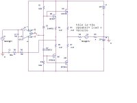
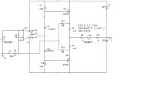
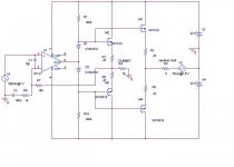
Re: altmann splif simulated
Darkfreniz,
I think that for this you should load the controlled output with a nominal 4 ohms resistor.
As it is now, the compromise looks better than the splif. I would have expected the splif to be better than the compromise, but I think it depends on the dummy load at least being present and nominal.
jan Didden
darkfenriz said:now we are about to simulate the splif enhancement of this amp
Darkfreniz,
I think that for this you should load the controlled output with a nominal 4 ohms resistor.
As it is now, the compromise looks better than the splif. I would have expected the splif to be better than the compromise, but I think it depends on the dummy load at least being present and nominal.
jan Didden
Dear Charles,
we are not talking about me and my beliefes, but rather about your SPLUF invention, and that's where you are comming into the picture! 🙂
Ouch.. I typoed again, the U letter is terrible close to I on my keyboard... 😉
Indeed we can also say output impedance, but saying it depends on the dummy load is like Pass would say the same but "it depends on the bias, amount of output transistor etc...", still don't answering the, in fact, answerable question.
You are hardly going to be belived on this forum sliding around with your answers/avoiding answering serious questions, but if that's your "marketing strategy", your wellcome... 😎
Still on a learning curve... Charles?
Cheers! 😉
we are not talking about me and my beliefes, but rather about your SPLUF invention, and that's where you are comming into the picture! 🙂
Ouch.. I typoed again, the U letter is terrible close to I on my keyboard... 😉
As for the SPLIF amp, the damping factor or better output impedance also depends on the dummy load and therefore is adjustable to a certain extend
Indeed we can also say output impedance, but saying it depends on the dummy load is like Pass would say the same but "it depends on the bias, amount of output transistor etc...", still don't answering the, in fact, answerable question.
You are hardly going to be belived on this forum sliding around with your answers/avoiding answering serious questions, but if that's your "marketing strategy", your wellcome... 😎
Still on a learning curve... Charles?
Cheers! 😉
Ultima Thule said:Indeed we can also say output impedance, but saying it depends on the dummy load is like Pass would say the same but "it depends on the bias, amount of output transistor etc...", still don't answering the, in fact, answerable question.
You are hardly going to be belived on this forum sliding around with your answers/avoiding answering serious questions, but if that's your "marketing strategy", your wellcome... 😎
Still on a learning curve... Charles?
Cheers! 😉 [/B]
Ultimo,,
please explain what exactly you want to measure.
Damping factor varies with speaker impedance. The output impedance of the Splif amp varies with the dummy load. It is adjustable, but it will still be higher than with a feedback amplifier.
A higher output impedance means a lower damping factor which means that the Splif amp will have a significantly lower damping factor than achievable with a conventional feedback amplifier given the same speaker load.
The Splif amplifer like any zero-feedback amplifier - by design - does not attempt to 'fix' or 'control' a voltage at the speaker output.
The output impedance is dependent on Ron of the Mosfet in their current working point, which in turn depends on VGS, which depends on what the speaker is throwing back or sucking in.
It is highly dynamic and I have no idea how to specify it, as it will be different with every different load and signal.
Does this answer your question ?
Charles 🙂
Charles said:[snip]The Splif amplifer like any zero-feedback amplifier - by design - does not attempt to 'fix' or 'control' a voltage at the speaker output.[snip]
Charles,
You know what I ask myself? Do you not really understand your own design, or are you telling things of which you are aware that they are not correct?
This fb design DOES try 'to 'fix' or 'control' a voltage at the speaker output'. The proof is the fact that you insist on a 'dummy' output stage identical to the real one, enclosed in a global fb loop, loaded with a dummy load that mimics the 'real' output stage loaded with the speaker.
If you would leave that out and take the fb directly from the Vas stage, you would be correctly saying that the fb doesn't try 'to 'fix' or 'control' a voltage at the speaker output'. But in this design, it DOES.
Jan Didden
Re: altmann splif simulated
should not there be a 8 ohm resistive load in there in the feedback cct ?
darkfenriz said:now we are about to simulate the splif enhancement of this amp
should not there be a 8 ohm resistive load in there in the feedback cct ?
Re: Re: altmann splif simulated
ooops, yes there should
i will correct it, but this won'tchange damping facts-only may improve linearity
mikelm said:
should not there be a 8 ohm resistive load in there in the feedback cct ?
ooops, yes there should
i will correct it, but this won'tchange damping facts-only may improve linearity
Re: Re: Re: altmann splif simulated
Interesting question indeed!
Would you mind do simulation with diffrent dummy loads, would be quite intersting to see what you get.
For instance 100, 8 and 4 Ohm.
Michael
darkfenriz said:
ooops, yes there should
i will correct it, but this won'tchange damping facts-only may improve linearity
Interesting question indeed!
Would you mind do simulation with diffrent dummy loads, would be quite intersting to see what you get.
For instance 100, 8 and 4 Ohm.
Michael
janneman said:This fb design DOES try 'to 'fix' or 'control' a voltage at the speaker output'. The proof is the fact that you insist on a 'dummy' output stage identical to the real one, enclosed in a global fb loop, loaded with a dummy load that mimics the 'real' output stage loaded with the speaker.
Hi Jan,
The dummy is in NO WAY meant to be identical to the real load.
It cannot be identical in any way.
It is meant to be a LINEAR load.
It also should in NO WAY mimic the real speaker load.
Again, it is meant to be a linear non-reactive load, very different from the real load.
The idea is that the speaker is driven - AS IF - it would be a linear non-reactive load with a constant (but adjustable through dummy resistor) impedance.
As the amp does not look at the speaker output it also does not try to correct or fix the voltage there.
You can specify output impedance of the dummy output section as this has feedback and will be quite low, but this may be different from the speaker output section depending on how the speaker behaves...
Hm... interesting... it drives the dummy section with low impedance... but does not correct for speaker EMF voltage.
So would it be correct to say that it can have a low impedance, but not necessarily a high damping factor... ?
Charles 🙂
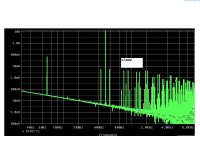
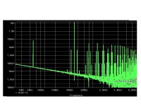
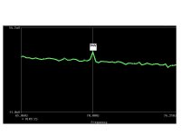
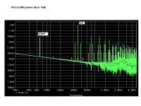
darkfenriz said:for 4 ohm dummy again nothing changed with damping the 'speaker' signal. more distortion again. bigger signal amplitude
All this would suggest that there is an optimum resistor size that may not be 8 ohms
- Status
- Not open for further replies.
- Home
- Amplifiers
- Solid State
- Is there anybody built a non feedback amplifier??