moamps said:
I agree lineup. I have some Lundhals left over from a previous build and that's one of the reasons I'm eyeballing this design as my next project. I was hoping someone would be able to share their listening impressions with us before I definitely decided to go ahead with a project like this.
Regards,
Milan
Milan
You should start a topic in Tubes forum.
Your topic should have the word 300B in the subject!
😉 Because them tube lovers are always very interested in 300B 😀
and any way to use these beasts.
Maybe even, if you are lucky, some would know of this very amplifier
and maybe even built something like it.
By the way,
Tube DIY Paradiso
has got many interesting, I think, SE tube project at the website
and several other 300B:
http://www.diyparadiso.com/index1.htm
Regards
lineup
Joachim_b said:I have been browsing quickly through this very interestion thread. I don't think, however, that anyone has mentioned Lars Clausens "The End". This kit has been very popular among diy'ers in scandinavia for many years. I have one of these myself and has always thought it looked like a very clever design.
Its latest incarnation looks like this: This one has emitter follower outputs.
http://www.lcaudio.dk/com/milldia.pdf
An older version is implemented with CFP's:
http://www.lcaudio.dk/temk2.jpg
Kind regards
Joachim
I know my reply is a bit late, but hey, I have two channels of that one (The End) here at home! I'm a bit scared to hook them up though since I melted some components and blew a tweeter last time I used them (some 14 years ago). I'm sure it was my own fault though.
Ayre AX-7e zero feedback
hi
Here is one commercial power amplifier
that shows we can build zero feedback amplifiers
with very good specifications .. and sound!
Think I will try to make it myself.
I will put my MultiSim into work 😉
Regards
lineup
---------------------------------------------------------------------------------
These measurements is from an independent reviewer website.
Not from Ayre own website.
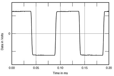
Ayre AX-7, small-signal 10kHz squarewave into 8 ohms
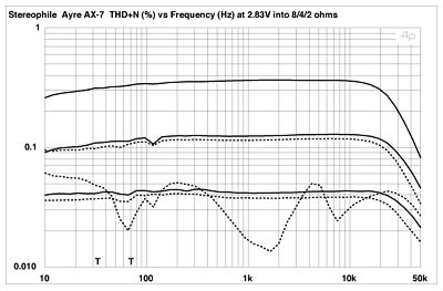
Ayre AX-7, THD+N (%) vs frequency (from bottom to top at 2kHz):
2.83V into simulated loudspeaker load, 8 ohms, 4 ohms, 2 ohms
Websources:
www.Ayre.com - AX-7e integrated amplifier
www.StereoPhile.com - Ayre AX-7 Review
hi
Here is one commercial power amplifier
that shows we can build zero feedback amplifiers
with very good specifications .. and sound!
Think I will try to make it myself.
I will put my MultiSim into work 😉
Regards
lineup
---------------------------------------------------------------------------------
AX-7e integrated amplifier
The Ayre AX-7 integrated amplifier ......
..... employing the same exclusive zero-feedback design
found in our reference products.
Specifications:
Power Output
60 watts per channel continuous into 8 ohms
120 watts per channel continuous into 4 ohms
Frequency Response
2Hz - 200 kHz
------------
These measurements is from an independent reviewer website.
Not from Ayre own website.
Ayre AX-7, small-signal 10kHz squarewave into 8 ohms
Ayre AX-7, THD+N (%) vs frequency (from bottom to top at 2kHz):
2.83V into simulated loudspeaker load, 8 ohms, 4 ohms, 2 ohms
Websources:
www.Ayre.com - AX-7e integrated amplifier
www.StereoPhile.com - Ayre AX-7 Review
Re: Ayre AX-7e zero feedback
And now I have started my investigations
and design of zero feedback amplifier stage
The Fourier analysis in my Attachment shows interesting things!
Harmonics:
.....................
2nd: -067 dB
3rd: -107 dB
4th: -101
5th: -104
6th: -105
7th: -106 dB
.........................
What is great, is the 3rd is -40dB from 2nd!!!
😎 This is extraordinary 😎
I think I have never seen anything like it .....
Set up. 1 kHz sinus.
One 2SK170GR in a very special 'lineup' circuit does the voltage gain.
Gain is +12dB. Set by 2 resistances.
Input 1 Vrms, Input impedance 100kOhm.
Output by a 2SK170 buffer, resistor biased
and output 4 Vrms into one 4k7 load.
I will continue to refine this circuit.
Then I be back with more details.
As you understand it is a line preamplifier.
lineup
lineup said:...shows we can build zero feedback amplifiers
with very good specifications .. and sound!
Think I will try to make it myself.
.
And now I have started my investigations
and design of zero feedback amplifier stage
The Fourier analysis in my Attachment shows interesting things!
Harmonics:
.....................
2nd: -067 dB
3rd: -107 dB
4th: -101
5th: -104
6th: -105
7th: -106 dB
.........................
What is great, is the 3rd is -40dB from 2nd!!!
😎 This is extraordinary 😎
I think I have never seen anything like it .....
Set up. 1 kHz sinus.
One 2SK170GR in a very special 'lineup' circuit does the voltage gain.
Gain is +12dB. Set by 2 resistances.
Input 1 Vrms, Input impedance 100kOhm.
Output by a 2SK170 buffer, resistor biased
and output 4 Vrms into one 4k7 load.
I will continue to refine this circuit.
Then I be back with more details.
As you understand it is a line preamplifier.
lineup
Attachments

After 5 years I have inovated and rebuilt my class A amplifier with output stage outside global NFB. Decreased CCIF IM and THD for large amplitudes. Biased at 1.65A iddle current. Yes, that's it! 😉
Pulse width modulation
How about a class D pulse width modulated switch-mode amplifier with a passive filter? Is there a hidden feedback somewhere?sreten said:
Its impossible to design any kind of amplifier, never
mind H-P, without some form of local feedback due to
inherent device parameters.
Non-linearities
There may be a hidden distraction in what you said.
A) Audio amplifiers are usually loaded with mostly linear loads, such as loudspeakers. Instead of great non-linearities, loudspeakers are reactive: Delays and inductances exist. The non-linearities and harmonic distortion appear with high sound pressure levels.
d) On the other hand a diode is very instant but also very non-linear.
So, in a nutshell: A diode and a loudspeaker are every way very different loads.
I don't love non-linearities. But some of them are more annoying than others.
Eva said:It's wonderful to see how people loves non-linearities
I suggest comparing the output waveforms of a global-feedback design and a no-global-feedback design both loaded with some non-linear evil load like a string of diodes resistors and capacitors in series/paralell
The results of the test are rather self-explaining and say a lot about which option has better 'load isolation'
There may be a hidden distraction in what you said.
A) Audio amplifiers are usually loaded with mostly linear loads, such as loudspeakers. Instead of great non-linearities, loudspeakers are reactive: Delays and inductances exist. The non-linearities and harmonic distortion appear with high sound pressure levels.
d) On the other hand a diode is very instant but also very non-linear.
So, in a nutshell: A diode and a loudspeaker are every way very different loads.
I don't love non-linearities. But some of them are more annoying than others.
Feedback or not
I have built passive attenuators using only resistors.
Gain is less than 1 but more than 0.
Is that an example of a feedback device?
dimitri said:> your argument applies to a resistor
where have you find resistor with current gain
I have built passive attenuators using only resistors.
Gain is less than 1 but more than 0.
Is that an example of a feedback device?
Re: Pulse width modulation
yes, there is negative feedback to the comparator to keep the transfer function of the modulator linear.
Nikolas Ojala said:
How about a class D pulse width modulated switch-mode amplifier with a passive filter? Is there a hidden feedback somewhere?
yes, there is negative feedback to the comparator to keep the transfer function of the modulator linear.
PMA said:After 5 years I have inovated and rebuilt my class A amplifier with output stage outside global NFB. Decreased CCIF IM and THD for large amplitudes. Biased at 1.65A iddle current. Yes, that's it! 😉
So are you saying the OP stage has local FB only and IP stage same?
How does it measure?
Terry
Re: Feedback or not
I addressed this issue a few years ago and it rears its head one more time. If you consult any peer-reviewed university text on discrete amps you will find that emitter degeneration and/or emitter followers inherently possess local feedback. If this bothers you, I ask then why do peer-reviewed texts and semiconductor makers state this?
A definition of feedback is in order. A zero feedback amp is one whose input consists entirely of an independent signal source and the amp's own output contributes nothing to the input. A change in output does not influence the input of the amp.
With emitter degeneration, local feedback, not global, is present. Also, global fb is usually of a *parallel* nature, whereas emitter degeneration is *series* type feedback. Let's say an input at the base of the bjt is a constant voltage source which increases in magnitude. This results in an increasing value of all 3 currents, ib, ic, and ie. The increased emitter current, ie, results in an increased voltage across the emitter resistor, Re. As a direct result, the emitter terminal's potential wrt ground is elevated.
The result is plain to see. The base is connected to a constant voltage source, let's say "vb". Any source resistance in the signal source plus any base resistance including internal rbb' can be represented as "Rb". Since vb is fixed, and ve has increased, then (Rb*ib + vbe) must *decrease* in accordance w/ Kirchoff's voltage law (KVL). If the sum of Rb*ib and vbe must decrease, then the 2 quantities cannot both increase, as their sum would also increase. The only way for the sum to decrease is either for both to decrease, or one increases while the other decreases more.
A bjt b-e junction is essentially a forward biased diode. An increase in current always incurs an increase in voltage, and likewise for a decrease. The diode I-V relation is monotonic, i.e. both I and V change in the same direction. Both ib and vbe must decrease. As a result collector current ic will likewise decrease. Remembering that ie is just ib + ic, ie must decrease as ib + ic decreases.
Hence an increase in ie, was translated into an increase in the voltage across Re, which increased ve, which decreased ib and vbe, which decreased ic, finally decreasing ie. As soon as ie increases for whatever reason, random noise, thermal, input signal, etc. Re forces ie to decrease. If ie decreases the result is that Re forces ie to increase.
Thus a change at the output, ie, forces the input, ib and vbe, to change in the opposite direction, negating the original perturbance. The output influences the input via Re, the emitter degeneration resistor. This is series feedback since we're summing voltages around a node. Global fb usually is parallel in nature, and sums currents at a node.
To eliminate series feedback, we don't "open the loop", rather we "short the node". If Re is shorted and the emitter terminal is directly connected to ground, there is no feedback. If the emitter current is perturbed, there is no corrective action. The input remains unchanged as the output has no inluence on the input.
It's pretty straightforward. If no Re is used, then the inherent re internal to the bjt provides a small amount of series feedback. The laws of circuit theory easily confirm this. What's the beef?
Nikolas Ojala said:
I have built passive attenuators using only resistors.
Gain is less than 1 but more than 0.
Is that an example of a feedback device?
I addressed this issue a few years ago and it rears its head one more time. If you consult any peer-reviewed university text on discrete amps you will find that emitter degeneration and/or emitter followers inherently possess local feedback. If this bothers you, I ask then why do peer-reviewed texts and semiconductor makers state this?
A definition of feedback is in order. A zero feedback amp is one whose input consists entirely of an independent signal source and the amp's own output contributes nothing to the input. A change in output does not influence the input of the amp.
With emitter degeneration, local feedback, not global, is present. Also, global fb is usually of a *parallel* nature, whereas emitter degeneration is *series* type feedback. Let's say an input at the base of the bjt is a constant voltage source which increases in magnitude. This results in an increasing value of all 3 currents, ib, ic, and ie. The increased emitter current, ie, results in an increased voltage across the emitter resistor, Re. As a direct result, the emitter terminal's potential wrt ground is elevated.
The result is plain to see. The base is connected to a constant voltage source, let's say "vb". Any source resistance in the signal source plus any base resistance including internal rbb' can be represented as "Rb". Since vb is fixed, and ve has increased, then (Rb*ib + vbe) must *decrease* in accordance w/ Kirchoff's voltage law (KVL). If the sum of Rb*ib and vbe must decrease, then the 2 quantities cannot both increase, as their sum would also increase. The only way for the sum to decrease is either for both to decrease, or one increases while the other decreases more.
A bjt b-e junction is essentially a forward biased diode. An increase in current always incurs an increase in voltage, and likewise for a decrease. The diode I-V relation is monotonic, i.e. both I and V change in the same direction. Both ib and vbe must decrease. As a result collector current ic will likewise decrease. Remembering that ie is just ib + ic, ie must decrease as ib + ic decreases.
Hence an increase in ie, was translated into an increase in the voltage across Re, which increased ve, which decreased ib and vbe, which decreased ic, finally decreasing ie. As soon as ie increases for whatever reason, random noise, thermal, input signal, etc. Re forces ie to decrease. If ie decreases the result is that Re forces ie to increase.
Thus a change at the output, ie, forces the input, ib and vbe, to change in the opposite direction, negating the original perturbance. The output influences the input via Re, the emitter degeneration resistor. This is series feedback since we're summing voltages around a node. Global fb usually is parallel in nature, and sums currents at a node.
To eliminate series feedback, we don't "open the loop", rather we "short the node". If Re is shorted and the emitter terminal is directly connected to ground, there is no feedback. If the emitter current is perturbed, there is no corrective action. The input remains unchanged as the output has no inluence on the input.
It's pretty straightforward. If no Re is used, then the inherent re internal to the bjt provides a small amount of series feedback. The laws of circuit theory easily confirm this. What's the beef?
Re: Re: Feedback or not
Hi
I strongly agree with you.
We have also the case of a emitter follower , that use 100 % negative feedback.
I can't understand the anti-feedback crusade...
Claude Abraham said:
The laws of circuit theory easily confirm this. What's the beef?
Hi
I strongly agree with you.
We have also the case of a emitter follower , that use 100 % negative feedback.
I can't understand the anti-feedback crusade...
In this context "zero feedback" is usually used in the the 'no loop feedback between stages' sense, local degeneration is still allowed.
the beef is a misunderstanding of how feedback operates. feedback it thought to increase high order harmonics and cause TIM (or DIM, or any number of nasty sounding acronyms for intermodulation distortion). actually it doesn't INCREASE higher order harmonics, but reduces lower harmonic products to the point where higer order harmonics become more noticeable in the residual. this is because of lower gain in the input stage at higher frequencies. all distortion is reduced by negative feedback, but higer frequency products are reduced less than lower frequency products, so a spectrum analyzer shows more high frequency products proportionally than would be seen with less feedback. the main problem with IMD is that an input stage with poor slew rate will not respond to the input signal fast enough to give an accurate rendition of the signal at the output, and so intermodulation takes place similar to what's desired in a superhet radio mixer stage, you get sum and difference signals (ie a 1khz and a 1.1khz signal have sums and differences of 2.1khz and 100hz). the slew rate of an amplifier would have to be VERY poor to produce any audible IMD. IMD was a problem back in the 60's and 70's when older designs produced poor results. with modern techniques and good designs, the problem is actually a thing of the past.
there is an urban legend that negative feedback continuously "recirculated" through an amplifier, but that's a complete misunderstanding of how analog electronics works. amplifiers "see" a single voltage at any single point of time, and amplifies that voltage. with a diff amp (LTP) the amplifier amplifies the difference between two voltages. it's like a lever. i think the "recirculation" legend is a product of the digital age, where people are used to thinking in terms of time slices and samples rather than a continuous instantaneous voltage with the simple characteristics of amplitude and time.
there is an urban legend that negative feedback continuously "recirculated" through an amplifier, but that's a complete misunderstanding of how analog electronics works. amplifiers "see" a single voltage at any single point of time, and amplifies that voltage. with a diff amp (LTP) the amplifier amplifies the difference between two voltages. it's like a lever. i think the "recirculation" legend is a product of the digital age, where people are used to thinking in terms of time slices and samples rather than a continuous instantaneous voltage with the simple characteristics of amplitude and time.
I completely agree, it's an area we aren't well equiped to grasp intuitively. My understanding is 'increased higher harmonics' refered to harmonic number though, not level. The reasoning is based on an example open-loop amplifier - ignoring for the moment if any realizable circuit meets the criteria - which generates a sharply defined harmonic distortion profile terminating at some number N. For simplicity, assume N=2, the circuit's distortion is purely 2nd harmonic and everything 3rd or higher is infinitely suppressed. Also assume a 3 port device: primary input, feedback return input and output.
In practice the port to which feedback is returned will have a non-linear transfer function and generate harmonics, otherwise we could just use the feedback port as the primary input and get perfect amplification. Assume the distortion profile of the feedback input is identical to the primary's. Here's where loop-think enters. With the feedback loop opened, 2nd harmonic distortion appears on the output node. When the loop is closed the second harmonic contribution of the primary input is driven into the feedback node. The feedback node can't perfectly correct the error and generates an added distortion component of the primary's 2nd. If the input signal is a 1 kHz fundamental tone, the 2nd harmonic generated by the transfer function from primary node to output is 2 kHz. That 2 kHz tone is further distorted by the feedback to ouput node transfer function, generating a 4 kHz harmonic. Closing the feedback loop essentially generates a 4th harmonic component of the primary input that wasn't present beforehand.
You're probably already aware of this reasoning, I just wanted to see if I could express it comprehensibly. I don't think it's this simple, nor independent of the amount of loop reduction used.
degeneration is feedback
I'm well aware that the phrase "zero feedback" has generally implied zero global feedback but local stage feedback is still present. I've stated this in other threads several years ago when the discussion was alive. I don't have a problem with the phrase "zero feedback" as long as the meaning is understood and agreed upon. The purpose of my treatise was to explain the feedback operating principle to those who claim that emitter degeneration is NOT negative feedback.
A comment was made that an amplifier "sees" only a single voltage. But that voltage can be and is a sum of more than one signal, input and output. For a diff amp, one terminal can be the input and the other is the output, and the difference gets amplified. Another example is an inverting op amp w/ feedback. The input is connected to R1, and the output to R2. The midpoint of R1/R2 is connected to the op amp's inverting input. The signal seen by the amp and amplified is a combination of the input and output, hence feedback is present. This signal is Vd, the input terminal difference, which gets multiplied by the open loop gain. But Vd is determined by both the input and output.
With emitter degeneration, I demonstrated that the base current ib and base-emitter voltage vbe, of a bjt stage is determined by both the input and output. Of course the amp only amplifies just one signal, but that signal is a combination of both input and output. That's all I was discussing.
Again, if "zero feedback amp" infers the use of local series feedback via emitter degeneration, but no global feedback, that's fine. I've already stated years ago that there should be no issues with this terminology. But let us not forget that "emitter degeneration" is a form of negative feedback. Peace.
Pjotr said:Hi,
IMHO splitting the feedback issue into circuits that has a feedback topology intentionally and devices with no intentional feedback components around is a non-issue. All active devices have internal feedback mechanisms, even a single triode has anode-grid feedback. The difference is that feedback internal to a device has usually much higher loop bandwidth but is still feedback, as the oscillating emitter follower (and source follower/cathode follower) proves.
It makes more sense IMHO to split into overall feedback and local feedback schemes.
Cheers 😉
Pjotr said:
as the oscillating emitter follower (and source follower/cathode follower) proves.
I would never have deduced the existence of this phenomenon if i had not just discovered its bizarre effect on my circuit yesterday. Unless I was experiencing some kind of illusion, the oscillation of the emitter follower pair of bipolar transistors was actually causing the stage power supply to invert.
When I placed a 100ohm resistor in series with the collector of the NPN transistor, it seemed to thwart the internal positive feedback loop.
Try connecting a 100ohm at the base, that should stop the oscillation. Have a read of Bob Pease's book.
Praise! said:Try connecting a 100ohm at the base, that should stop the oscillation. Have a read of Bob Pease's book.
I don't have his book and don't foresee getting access to it. 🙂 I believe in free information for everyone. I could maybe have the library send for it from the main branch, but I use the Internet almost exclusively these days. I don't really want to read it in PDF format either, even if I had high speed Internet and could download it in high resolution for free. That is because my Acrobat reader doesn't provide the option of reading white text on a back background.
But I see how separating the bases with a resistor could prevent the oscillation. My impression is that if lower current is acceptable in one of the collectors, it could give better results. It should maintain the following effect a little better, though it lowers the input impedance.
- Status
- Not open for further replies.
- Home
- Amplifiers
- Solid State
- Is there anybody built a non feedback amplifier??