1) I think Vbe matching is a real problem if you use the darlington as the last stage output transistors. There is no way around it in parallel output darlington transistor situation. In normal discrete 3EF, you use one one transistor each for the first and second EF to drive 4 or 5 power BJT. So the first two Vbe is already matched ( you only have one transistor each in the two pre driver stage). Even if you hand pick, each parallel darlington might not have the same temperature. Now you have -4.4mV/deg C to to deal with.
2) If you run Class AB with parallel darlingtons. When you go from Class A to Class B, both transistor inside the darlington have to turn off. So you automatically have more crossover distortion.
3) Using darlington as pre-driver avoid all the problems above. You don't parallel in pre-drivers, so you don't have matching problem as in 1) above. You can bias the pre-drivers so they never turn off. So they literally work in Class A 100% of the time.
Member
Joined 2009
Paid Member
I agree, parallel outputs favours discrete power devices; Darlingtons are best suited to single output pairs. There are many amplifiers that would be just fine with single outputs.
If you download Leach's Lo Tim papers and read the section on pre-driver, driver and output currents you will find that the driver current and the pre-driver currents vary a lot. And the driver eventually turns to a constant current, which means it is no longer controlling the output. The driver is idling along for part of the waveform and NOT in ClassA, the other driver is active and doing all the controlling...................
Now I am contemplate using darlington for pre-driver stage. It should never be turn off so no cross over distortion to talk about. Also, the current variation is much smaller than when using in output power transistor, so hfe stays quite constant at range of say 50mA to 200mA.
What do you think?
.............
Use a similar analysis for your three stage output and examine the CURRENTS in the three devices as the output moves from V+peak to V-peak of a sinewave output into a resistive dummy load.
BTW, at peak transient output a 100W into 8ohms amplifier can exceed 15Apk. The driver output current can approach 1Apk to meet this transient demand. That in turn puts a big demand on the pre-driver. The saving grace is that these transients are very short duration and thus have very low heating effect. It's hFE droop at very high current that becomes the critical factor.
Last edited:
It's hFE droop at very high current that becomes the critical factor.
This is the problem with darlingtons. Beta droop in the output device has some effect on distortion, but beta droop in the *drivers* is much much worse. And beta at very low currents is nonlinear as well. The typical fix for that in an EF2 (EF3) is to bias the driver transistor up so the very low current region is avoided. This requires a low Rbe value, much lower than what they typically stick in a monolithic darlington. And the proper place to connect it is from output tranny base to output rail, inclusive of the output device emitter resistor. With monolithic darlingtons you don't get that option at all.
I can't find any other article other than this http://users.ece.gatech.edu/mleach/lowtim/. I read the Leach The Leach Amp - Output Stage, I did not see any mention on that.If you download Leach's Lo Tim papers and read the section on pre-driver, driver and output currents you will find that the driver current and the pre-driver currents vary a lot. And the driver eventually turns to a constant current, which means it is no longer controlling the output. The driver is idling along for part of the waveform and NOT in ClassA, the other driver is active and doing all the controlling.
Use a similar analysis for your three stage output and examine the CURRENTS in the three devices as the output moves from V+peak to V-peak of a sinewave output into a resistive dummy load.
BTW, at peak transient output a 100W into 8ohms amplifier can exceed 15Apk. The driver output current can approach 1Apk to meet this transient demand. That in turn puts a big demand on the pre-driver. The saving grace is that these transients are very short duration and thus have very low heating effect. It's hFE droop at very high current that becomes the critical factor.
Can you explain a more on Rbe value?This is the problem with darlingtons. Beta droop in the output device has some effect on distortion, but beta droop in the *drivers* is much much worse. And beta at very low currents is nonlinear as well. The typical fix for that in an EF2 (EF3) is to bias the driver transistor up so the very low current region is avoided. This requires a low Rbe value, much lower than what they typically stick in a monolithic darlington. And the proper place to connect it is from output tranny base to output rail, inclusive of the output device emitter resistor. With monolithic darlingtons you don't get that option at all.
I am thinking about bias the pre-driver at 50mA to even 100mA so the current variation is small to keep beta constant.
Attachments
That one serves the same purpose as Rbe - the 15 ohms from base to base. Some EF2/3's do it this way. The low value keeps the driver current from falling below some value. I usually use 22 ohms base to base or 10 ohms base to output, which puts it over 50mA. This even makes TIP transistors or MJ15xxx's well behaved. They usually stick a higher value inside a darlingon and the driver current can fall to much lower values. Useful for overall efficiency, but makes the beta curve even more of a haystack. And since that connection is unavailable there is nothing you can do about it.
Ah, you mean the internal resistance from the emitter of the first transistor(the first EF) to the second transistor (second EF being driven by the first). I saw the typical resistor value is only 80 to 100 ohm This only pull 7mA from the first transistor.That one serves the same purpose as Rbe - the 15 ohms from base to base. Some EF2/3's do it this way. The low value keeps the driver current from falling below some value. I usually use 22 ohms base to base or 10 ohms base to output, which puts it over 50mA. This even makes TIP transistors or MJ15xxx's well behaved. They usually stick a higher value inside a darlingon and the driver current can fall to much lower values. Useful for overall efficiency, but makes the beta curve even more of a haystack. And since that connection is unavailable there is nothing you can do about it.
I can come up with a few reasons
There is no proven design so far in a working condition that operates in class AB with more than pair ... so you got a power issue for starts
A4O works in higher bias than class AB so it doesn't count for an example AB 100 was never made in "massive " scale by Diyers so we also do not have any examples with that . To my opinion it could have stability issues ....depending on the choice of parts and implementations
Ft is low for today's standards
In total beta is too high ... combine this with reactive load such is a speaker with cables and so on and all forms of oscillation is waiting for you around the corner
Darlingtons are not easy to stabilize in circuits like audio amplifier anything that might happen in the input of the transistor will be amplified way too many times ..... anything will mean :
PSU related dirt , audio signal related dirt ,input related problems output related problems
Soa is poor in reality
Suppose that you like to work with TIP 142 147 where the fu*** you are going to get specs that are needed for a proper design , each and every datasheet presents a variety of specs, while none of them states cob and ft ( for 142-147 family ) ...choose at your own risk
There is a big issue when you cannot arrange the relation between the driver and the output part ....
In reality all elektor circuits all smart kit circuits all velleman circuits all philips and all B&O circuits that was based on 142-147 or cousins BDV 66-67 failed in long time run ...
Member
Joined 2009
Paid Member
Never mind those old things Sakis, look at what is currently in mass manufacture and is used by Pioneer (and Denon). Made by Sanken.
http://www.semicon.sanken-ele.co.jp/sk_content/2sd2390_ds_en.pdf
Ft = 55 MHz
Cob = 95pF
Hfe doesn't droop until Ic > 7A at 25degC
Even the older Darlingtons have created pleasure for folk:
http://www.diyaudio.com/forums/solid-state/133189-my-first-diy-amplifier-20-years-go.html
http://www.diyaudio.com/forums/solid-state/71292-lab10-audio-amplifier-project.html
and what about the well-regarded Sentec PA9 amplifier from Sweden: http://user.faktiskt.se/RogerGustavsson/Sentec PA-9.pdf
I believe JLH also used them.
Last edited:
If one were to use Darlingtons, because obviously it is possible, those are pretty good. Also the Darlingtons you use might be these:
Compare with something like a TIP100 or something like that...
That being said, I had to experiment with the idea of using cheap Darlingtons a bit and did make a pretty good amp using TIP100/105 Darlingtons. The thread is HERE. It sounded really good and I was quite surprised. I had to test the theory that these devices 'could' be used as outputs against the common knowledge that they are no good as outputs in class AB. The result I came to is that the answer is yes, BUT (there is always a 'but'😀) the circuit has to be designed around the device characteristics to work well, and that means something like the amplified diode circuit as the driving stage.
Attachments
Last edited:
Yeap the rush was the same when the SAP 15 family hit the market that with the extra pins and diodes wanted to solve the thermal stability issues and the thermal tracking issues of the first darlington produced result ??? smoke if pushed ...
will see about the newer ones time will tell
will see about the newer ones time will tell
Member
Joined 2009
Paid Member
BUT (there is always a 'but'😀) the circuit has to be designed around the device characteristics to work well, and that means something like the amplified diode circuit as the driving stage.
And that would be good advice to folk intent on taking a design for LATFET outputs and wanting to drop in MOSFETs, or many other interesting changes that I've seen people try 😱
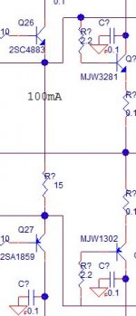
At this point, I am going to just do conventional 3EF. I already drew the rough schematic and posted here for comments. http://www.diyaudio.com/forums/solid-state/268265-please-comment-my-ops-design.html. There are mistakes. But my plan is when I have time, I'll change Q26 and Q27 to darlington by Sanka that is 50MHz, then just jumper base to emitter of Q20 and Q21 and adjust the bias to try it out. That is if I get to it.
I think using it as pre-driver will work IF I draw heavier current. I am planning to run 50mA to 100mA even for the pre-driver to ensure the speed of charge and discharge the input capacitance of all the power BJTs. High current also keep the variation of current low to keep beta constant.
I think using it as pre-driver will work IF I draw heavier current. I am planning to run 50mA to 100mA even for the pre-driver to ensure the speed of charge and discharge the input capacitance of all the power BJTs. High current also keep the variation of current low to keep beta constant.
Example of commercial design, utilizing MJ11016/11015 Darlingtons >Classe Audio DR-3< - schematic is there. This is a class A one - designed to run at 2.5A per output pair. 10A in total 😱
Note the output connectors (picture in the brochure). Also, powerhouse in the garden is recommended in general for better performance
Note the output connectors (picture in the brochure). Also, powerhouse in the garden is recommended in general for better performance
In the early years when i was collecting and recording data from various equipment with darlington that failed ( trust me a quiet long list ) i have come across the A40 article and study a bit on it .
I can describe my thoughts like that :
It seems that if highly biased darlingtons are ""too busy "" to oscillate ... or in other words cook them hot enough and you solve the thermal stability issues. The velleman/elektor circuit uses Miller caps in the region of 560pf to preserve stability and only one pair in the output biased in class AB
In the A40 you have 4 outputs which is far more risky in terms of oscillation and thermal behavior and no miller compensation at all .... Whats the catch here ?????? I have even constructed one A40 with ""anything available "" parts and proved to be a monster of stability !!
I have placed my thoughts as a question to the one and only never got an answer though ...
Kind regards
Sakis
Good example also might be the STR D series from Sony that uses MP and MN Darlingtons that a guarded by the very moderate 22pf Miller caps and zener diodes in the base of every transistor alla mosfet style
Point is that these type of models run to almost 60 volt rails which is almost astronomical driven by IC that probably has in a way a guarded bandwidth /speed ...
Application is low fi cheapish home theater amplifier and this one also has a long history of output fail even though duty is not full power ( surround back ch for example )
In the amplifier protection monitors short circuit , overload , over drive and so on ...
Kind regards
Sakis
Finally a good example of our thoughts in general might be the alchemist forseti that has a unique output stage that is made CFP style and includes 4 drivers and 4 outputs
Even though discrete and made by 15mhz ft parts ,one may think of it as an amplifier that has 2XTIP 142 and 2X TIP147 in the output configured CFP style Impossible to stabilize as was, and that was made with slow drivers for starts ..
CRC stiff power supply plenty of uncontrolled bias bootstrap in the VAS and a good preamp behind it made the amplifier sound nice in total but too many guards in the output stage actually gave the amp a weird tonal result a thing that either you love or you hate ....
Point of all the above was the stability issues
Kind regards
Sakis
In the early years when i was collecting and recording data from various equipment with darlington that failed ( trust me a quiet long list ) i have come across the A40 article and study a bit on it .
I can describe my thoughts like that :
It seems that if highly biased darlingtons are ""too busy "" to oscillate ... or in other words cook them hot enough and you solve the thermal stability issues. The velleman/elektor circuit uses Miller caps in the region of 560pf to preserve stability and only one pair in the output biased in class AB
In the A40 you have 4 outputs which is far more risky in terms of oscillation and thermal behavior and no miller compensation at all .... Whats the catch here ?????? I have even constructed one A40 with ""anything available "" parts and proved to be a monster of stability !!
I have placed my thoughts as a question to the one and only never got an answer though ...
Kind regards
Sakis
Hi Sakis, I agree with regards to thermal stability. At such a high idle current level, you don't need to maintain the quiescent current precisely. Federico Paoletti uses a thermo-resistor to avoid a thermal runaway - rather simple solution, but enough for the purpose 😎
In terms of compensation - he gets away with a single 30p cap from the VAS output to (-) input... not that bad.
Last edited:
- Status
- Not open for further replies.
- Home
- Amplifiers
- Solid State
- Is there any reason why people don't use darlington power transistor?