hollowman said:About as much as your cryptic rhetoric. But, seriously, the burden of proof is on both Philips and its challenger. Otherwise, one is shouting in a vacuum.
You people, you parachute into this stuff without a clue, no hinterland to speak of, then come up with the tosh above when told you are in error.
Frankly, the burden is all on you to inform yourself. Philpoole disputed what I said and I responded. That you fail to understand what you are dealing with is no concern of mine.
You may be MOSTLY correct in this matter. However, your lack -- habit, IMO -- of providing short but not terse -- responses, IMO, undermines whatever point you're trying to get across. That, IMO, is not in the didactic spirit of DIY, even tho’ that may be your “style”.rfbrw said:You people, you parachute into this stuff without a clue, no hinterland to speak of, then come up with the tosh above when told you are in error.
Frankly, the burden is all on you to inform yourself. Philpoole disputed what I said and I responded. That you fail to understand what you are dealing with is no concern of mine.
Phil, in this thread, posted complete descriptive responses and acknowledged his strengths and weakness, failures and successes. He adhered very much to the Scientific Method. Ultimately, he achieved better-than-7220 success with TDA1541A + PMD100: no doubt, the result of hard work and true problem-solving. That's DIY.
I somewhat retract my earlier burden-of-proof comment in light of your response. In fact, rfbrw, the burden-of-proof (of how and why the TDA1541A is not 8x capable) is now mostly on you.
If you are incapable of extracting data from a datasheet, that is your problem. The answers are there for those who do not need to be spoon fed.
One of the main objectives of a DIY forum, and online communites, is to explain -- using clear language -- myriad, topical concepts to all un- or under-informed, which includes newbies. If that is "spoon feeding" so be it -- we were all infants once, and continue to be in novel circumstances.rfbrw said:If you are incapable of extracting data from a datasheet, that is your problem. The answers are there for those who do not need to be spoon fed.
As far as the TDA1541A datasheet...
Figs 3 and 4 (p. 8, 9) show, FWIW, THD distortion for both 4x and 8x. -60dB distortion looks better for 8x; 0dB looks better for 4x.
hollowman said:One of the main objectives of a DIY forum, and online communites, is to explain -- using clear language -- concepts to all un- or under-informed, which includes newbies. This is not spoon feeding.
It is one thing to explain in order to allow others to understand and create and it is quite another to expect others to do the understanding and creating for you.
As far as the TDA1541A datasheet...
Figs 3 and 4 (p. 8, 9) show, FWIW, THD distortion for both 4x and 8x. -60dB distortion looks better for 8x; 0dB looks better for 4x.
This neatly illustrates the problem. You have chosen to ignore vast chunks of the datasheet for reasons that totally elude me. Do you not think that if it is put to you that you are violating the specs, it might be a good idea to study said specs?
Hi,
I disputed you rfbrw because I don't see any evidence in the datasheet, and my TDA1541A is working fine with 8x oversampling.
Looking at the datasheet. Clues that suggest to me the chip does 8x oversampling...
"FEATURES: 4x or 8x oversampling possible" - okay, it says possible, I guess that's all dependent on the sampling frequency involved.
"QUICK REFERENCE DATA: tcs current settling time to +/- 0.5uS" - that's okay because 1/352kHz is about 2.5uS.
"BR: Input bit rate at data input (pins 3 and 4), MAX 6.4Mbps, fBCK Clock frequency at clock input 6.4MHz" - That's also okay, I'm clocking in data at 5.6Mhz.
You realise I'm clocking data into DATAL and DATAR?
I don't think there's much else in the datasheet that might be an obstacle for my application.
I appreciate you believe otherwise, and I haven't disregarded it. I just don't see the evidence myself.
Cheers,
Phil
So dont "elude" us ... Other than the items Phil noted, why don't you LIST all that I have "ignored", with appropriate page numbers. I have no problem with being stood corrected if I can get a better-sounding D/A or CDP!rfbrw said:This neatly illustrates the problem. You have chosen to ignore vast chunks of the datasheet for reasons that totally elude me. Do you not think that if it is put to you that you are violating the specs, it might be a good idea to study said specs?
Belief has nothing to do with it.
The PMD100 uses 32 bits per frame per channel. Each data bitcell requires 1 BCKO cycle hence 8x32x44100=11M2896. That is a BCKO cycle time of 88nS. The TDA1541A specifies Tcy min as 156nS.
True, it is in this case a burst clock but the data rate remains the same when active.
Now a word or two on the topic from somewhere else.
We do not want to go there do we ? in the eyes of the ones that post there the whole world is ignorant except themselves. Pretty much the same behaviour as...
well every word is one too many on the subject.
well every word is one too many on the subject.
Trust me to be looking at the wrong datasheet!
So, its not within specification, but works a treat for me. If it wasn't working due to this spec mismatch, you'd know about it.
So, its not within specification, but works a treat for me. If it wasn't working due to this spec mismatch, you'd know about it.
jean-paul said:We do not want to go there do we ? in the eyes of the ones that post there the whole world is ignorant except themselves. Pretty much the same behaviour as...
well every word is one too many on the subject.
The point of the visit to the other place is that the originator of the schematic in question freely acknowledges the timing violation.
As for the rest, glasshouses and stones, JP, glasshouses and stones.
So.
Technically, the TDA1541A is perfectly capable of 8x oversampling. Even at 44.1Hz.
But, the burst mode of the PMD100 (in order to accommodate longer word lengths if requested) does mismatch with the datasheet of the TDA1541A. Fair point, its not working within its specified limits. All bets are off. But I do have two of them working well in these conditions. So I'd argue that, probably due to the fact that the average input rate is unaltered, it can cope with these bursts of data.
I do wonder if the limit on 6.4MHz is actually limited by something further along the chain, rather than the input circuitry, and/or based on constant throughput.
That's twice I've been accused of being a parachutist, yet I'm rubbish at jumping out of planes. I do however have a degree in electronics. I admit I have specialised since in a career more focussed in software, but I do still have a vague idea of what I'm doing.
I do, sort of at least, understand what I am dealing with.
(no doubt, the degrees these days aren't what they used to be...)
I'm very flattered hollowman, but it really was more laziness than hard work 😀 But I'm willing to report my failures as well as success, as it's a crucial part of the learning process.
Technically, the TDA1541A is perfectly capable of 8x oversampling. Even at 44.1Hz.
But, the burst mode of the PMD100 (in order to accommodate longer word lengths if requested) does mismatch with the datasheet of the TDA1541A. Fair point, its not working within its specified limits. All bets are off. But I do have two of them working well in these conditions. So I'd argue that, probably due to the fact that the average input rate is unaltered, it can cope with these bursts of data.
I do wonder if the limit on 6.4MHz is actually limited by something further along the chain, rather than the input circuitry, and/or based on constant throughput.
You people, you parachute into this stuff without a clue, no hinterland to speak of, then come up with the tosh above when told you are in error. Frankly, the burden is all on you to inform yourself. Philpoole disputed what I said and I responded. That you fail to understand what you are dealing with is no concern of mine.
That's twice I've been accused of being a parachutist, yet I'm rubbish at jumping out of planes. I do however have a degree in electronics. I admit I have specialised since in a career more focussed in software, but I do still have a vague idea of what I'm doing.
I do, sort of at least, understand what I am dealing with.
(no doubt, the degrees these days aren't what they used to be...)
Phil, in this thread, posted complete descriptive responses and acknowledged his strengths and weakness, failures and successes. He adhered very much to the Scientific Method. Ultimately, he achieved better-than-7220 success with TDA1541A + PMD100: no doubt, the result of hard work and true problem-solving. That's DIY.
I'm very flattered hollowman, but it really was more laziness than hard work 😀 But I'm willing to report my failures as well as success, as it's a crucial part of the learning process.
Yeah, Guido (whom I forgot to mention) did do a lot of the leg-work, so we must give him a lot of the credit.philpoole said:I'm very flattered hollowman, but it really was more laziness than hard work 😀 But I'm willing to report my failures as well as success, as it's a crucial part of the learning process.
I've still got a few PMD100s lying around, and despite my earlier remarks (no doubt due to my own neglect of some aspects of tweaking this design), I plan on using them.
rfbrw's comments are noteworthy. I simply wish his tactics were a bit more terse, less dodgy. In fact, it's partly due to his comments, that my future implemetaion of PMD100 will be mating it with, say, PCM63 or AD1862 -- not TDA1541A.
Forward...!
One more little thing - for chips designed to work together - they don't interface very well without a bit of work! Find the long 'TDA1541 thread in this forum of more details, but the key tweak is to use RC decoupling in the signal lines between these two chips to reduce HF noise injection into the dacs substrate (1K/10pF was suggested)*. Your Arcam already has some resistors in place in these lines, so definitely add small caps (10-22pF) to digital ground at the 1541 input pins. It helps a surprising amount.
*this is because the 7220 swings 5v pk-pk on its outputs, and the 1541 only needs a tiny current centred c1.4v to switch - it's a current-routing logic; the excess voltage swing just pushes HF currents into the dac.
Hi there,
how that may be done?
Like in red or in green or something else? Also, with a flipflop to divide the XO frequency, is it the right place to feed the DAC?
Have mercy if these are stupid questions 😉
Matthieu
Attachments
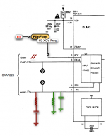
I would guess neither... the resistors should be in series with the lines. The caps go to ground, to form a low pass RC filter.
Hi Pars,
I'll need to cut the track then and as it's easy to do and undo I'll give a try.
Regards,
Matthieu
I'll need to cut the track then and as it's easy to do and undo I'll give a try.
Regards,
Matthieu
You are right, it's an RC low pass filter, confirmed in the TDA1541 thread.
Thanks. Not found about the clock feed, maybe it's so obvious nobody dare confirm or even ask...
Thanks Pars!
Thanks. Not found about the clock feed, maybe it's so obvious nobody dare confirm or even ask...
Thanks Pars!
Well after the "find by yourself or die" tensions and my lovely stupid question, seems I've killed the thread!
I think we can't all spend our lives in datasheets, some like to try and understand, that does not make the ones who follow and do -like me- people to get rid of. I hope so or that means mean stories of "superior peoples".
Question, any evidence that leaving the RC on BCK, 1K/10pf (working nicely) but fed by a flipflop instead of the SAA7220 will do any hamr to the clock signal? As far as I can understand the 5V output is too high also for the TDA?
For a stupid guy just wanting to get better music in his house for few money and not becoming an engineer most of friends around don't understand what I'm talking about. Or money is "better" than "datasheet & electronic knowledge".
Oh yes that's right, I've got none of both, like 90% of people of this planet. Please don't kill me.
- Home
- Source & Line
- Digital Line Level
- Is the SAA7220P/B really that bad ?