Hi there @camplo,
i wonder if it would make sense to make a kind of executive summary of the outcome of this 660+ posts thread.
if i were you i would do the following
A )
short sketch of your PPSL + mid - high range horn construction
B )
short description of the chassis used
C )
measurements
- SPL frequency response curve and CSD / WCD of PPSL
- SPL frequency response curve and CSD / WCD of mid -high range horn
D )
description of the crossover used with
- SPL frequency response curve of both together 0 / 15 / 30 degree
E )
which are the unanswered questions left
If this is too much effort for you i understand, but this would really help i think
So far - so good, Stefano
I want to do all the things but I have to finish the project first. Its supposed to be 50f today and the next few days, at about noon I want to go out and stain the horns. I have the horn stands sorta kinda finished. Then I can actually set it up outside for measurements.
Oh yeah, theres the other part where I would like design my own horn and 3d print it. I think I could take the basis of what I have and improve upon it to at least get rid of the FR modulation near cutoff.
Oh yeah, theres the other part where I would like design my own horn and 3d print it. I think I could take the basis of what I have and improve upon it to at least get rid of the FR modulation near cutoff.
Last edited:
A vented enclosure doesn't do impedance matching. You trigger a resonance. Yes the membrane has to do less work cause of the resonance but that's still not impedance matching.So no then?
" The horn can be thought of as an "acoustic transformer" that provides impedance matching between the relatively dense diaphragm material and the less-dense air. The result is greater acoustic output power from a given driver.[1]"
By this definition every vented enclosure is a horn lol.
That's not being open minded it's simply using terms wrong. A vented enclosure no horn. And a resonating pipe is also no horn.
At least don't unsettle beginners when you don't recognise the difference ...
A horn doesn't do impedance matching, You trigger a resonance. Yes the membrane has to do less work cause of the resonance but that's still not impedance matchingA vented enclosure doesn't do impedance matching. You trigger a resonance. Yes the membrane has to do less work cause of the resonance but that's still not impedance matching.
At least don't unsettle beginners when you don't recognize the difference...
Wait till you figure out you are wrong, This is what happens when you regurgitate information that you do not fully understand. There are at least 2-3 waveguide experts watching this thread right now.... which one can you convince that impedance matching (which is a misnomer) is separate from quarter wave resonation?That's not being open minded it's simply using terms wrong. A vented enclosure no horn. And a resonating pipe is also no horn.
Questions to ask yourself....
Matching the impedance of what?
Whats the impedance of air?
Does a horn ever reach that impedance?
before I get my head chopped off, I am definitely not the expert and am still learning =) which is still better than pretending to know. The resonation of a horn, is caused by an impedance mismatch. A horn is a impedance mismatching device lol!
Last edited:
??? Your "logic" is quite amusing...according to my logic, "a building for human habitation" that doesn't have a kitchen, living room, or bathroom... is a truncated house.
The house have many components (rooms, doors, windows...) and if one whole room (kitchen) is missing, you may call that house a truncated - but not the other way around! So, bathroom (or kitchen), a single door, or single window, or (single) kitchen sink is not a truncated house - the same as why the PPSL is not a truncated horn.
Last edited:
I agree. AS PPSL has a throat and a mouth.Your "logic" is quite amusing...
Helm Holtz resonance doesn't include standing waves??? I am still learning how to look at it... but sure, the enclosure becomes the throat, and the bass reflex tube its self is a throat, and where it opens to the outside would be the terminus aka mouth 😀bass-reflex tube is the mouth
throat 2: a passageway, a constriction, or a narrowed part
Entrance and Passageway for sound energy...Mouth 3: something that resembles a mouth especially in affording entrance or exit
Like the mouth of a throat lol.... its just an opening.
Terminus 3: a final goal : a finishing point
The end of the Line...the end of the passageway... etc...
Words are fun
Last edited:
What I can't figure out is what causes coupling in the line.... I understand that if you make a quarter wave resonator with an expanding line it allows for a larger mouth which lowers the Q of the resonance, which is a fancy way of saying it spreads out the resonance, instead of being more of a one note wonder like a constant CSA quarter wave resonator.... I am beginning to understand why the initial reflection is caused, that is quarter wave resonance, but it seems reflection happens and the coupling happens at the extent of the impedance mismatch..... So you have reflections and an air mass that matches the velocity of the diaphragm all existing in the same axial length???? Thats fine... but what causes the coupling to extend only a certain distance from the diaphragm? its as if quarter wave and coupling are directly connected. You cannot separate coupling from quarter wave resonance.....but I cannot see what causes the coupled air to move at the same velocity as the diaphragm only for a certain axial length....
The interesting aspect that is easily seen is that a horn, lowers the acoustical impedance of the driver.... through the act of Coupling. By coupling with air, a larger "diaphragm" is created which simply increase Volume portion of VV.
The interesting aspect that is easily seen is that a horn, lowers the acoustical impedance of the driver.... through the act of Coupling. By coupling with air, a larger "diaphragm" is created which simply increase Volume portion of VV.
Camplo is not fond of sticking to standard scientific terminology. He likes to invent his own.That's not being open minded it's simply using terms wrong.
Basically a PPSL is a fourth order bandpass nothing more, nothing less. No need to give it a new name.
I was hoping to get some answers to my question here...What I can't figure out is what causes coupling in the line.... I understand that if you make a quarter wave resonator with an expanding line it allows for a larger mouth which lowers the Q of the resonance, which is a fancy way of saying it spreads out the resonance, instead of being more of a one note wonder like a constant CSA quarter wave resonator.... I am beginning to understand why the initial reflection is caused, that is quarter wave resonance, but it seems reflection happens and the coupling happens at the extent of the impedance mismatch..... So you have reflections and an air mass that matches the velocity of the diaphragm all existing in the same axial length???? Thats fine... but what causes the coupling to extend only a certain distance from the diaphragm? its as if quarter wave and coupling are directly connected. You cannot separate coupling from quarter wave resonance.....but I cannot see what causes the coupled air to move at the same velocity as the diaphragm only for a certain axial length....
The interesting aspect that is easily seen is that a horn, lowers the acoustical impedance of the driver.... through the act of Coupling. By coupling with air, a larger "diaphragm" is created which simply increase Volume portion of VV.
Lord have mercy, it took a while, I had my hunches but I finally figured it out. In the oscillation of a cycle, max amplitude is reached for the first time at 1/4 wavelength. This pressure antinode causes conditions for reflection, and also causes a discontinuity of the coupled air column... Horns are impedance mismatching devices. Through the mismatching of impedance quarterwave resonance is able to occur... the standing wave that is created lowers acoustical impedance by way of constructive interference that accumulates pressure to a higher amplitude than it would otherwise.
You, are, welcome, lol

You, are, welcome, lol
So the other thing I am trying to figure out... the coupled air column... it should move with the diaphragm... The beginning of the line is the diaphragms face... as it moves back n forth, so does 1/4wl where the antinode lives.... not sure if it works that way, but it sounds right.
No, it doesn't:Helm Holtz resonance doesn't include standing waves???
https://en.wikipedia.org/wiki/Helmholtz_resonance
Please stop learning how to take a different look at the words we all know. So, no - the (loudspeaker) enclosure can not possibly look like a throat. Unless... is smoking weed legal in your country?I am still learning how to look at it... but sure, the enclosure becomes the throat,
Believe it or not - this is a doorway, as all "non-smoking" people are recognizing it:throat 2: a passageway, a constriction, or a narrowed part
Entrance and Passageway for sound energy...
Doorway definitely is not this (bass-reflex tube):
Last edited:
Impossible, because you are not using English words in a meaning we all know...I was hoping to get some answers to my question here...
Hi again @camplo !View attachment 1290291
This is a small detail, there is still a slot resonance, but within the last page or two, we are discussing that Cutoff, is not a real thing, in terms of what has been suggested in history. The slot resonance is no different than the quarter wave resonance of a horn. The resident expert, who has much higher standards than myself, but more importantly, the education to back it up, says "Cutoff" is a fictional idea that doesn't exist in reality ".... We are discussing the cutoff, he goes on to say "The issue is that all waveguide/horns show very low efficiency at LFs (below "cutoff" if you must) and as such require ever more excursion from the driver". In this case, the drivers in the horn, have much more LF efficiency to give, as they are not relying on the horn to generate it, as a compression driver does. As of most recently, he points out that if there is another issue, it would be of directivity, with the potential issue of a non constant directivity. Being that we are dealing with such low frequency, there is even less of a chance of issue.
Ok, I am getting a little ahead of myself, With an offset horn, there is the known issue of a flawed FR, due to cancellation via reflection. I have this issue, to a certain degree. and I am working on fixing it... as there are several ways to address it.
If your sketch is more or less right in the proportions here my comments with this.
A )
Closed box behind the bass chassis
- if we talk about a PA 18 inch chassis even with 50 liters closed box behind it the resonance of the chassis will rise from 30 Hz free air to 70 - 80 Hz
B )
- the slot loaded effect is nearly impossible to simulate, we would need to see some measurements of this
- a first educated guess of mine is that with the slot loading you achieve a slight decrease of the bass chassis Fr compared to the Frcb frequency
- the most important thing is probably that with the slot load mouth with this shape you achieve a closer distance between bass and horn
- this effect is not really so important with a cutoff of the horn < 340 Hz with a wavelength about 1 meter
C )
for a predictable behaviour with a simulation the construction looks different, here an example with 18 inch PA chassis from Visaton
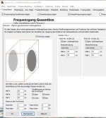
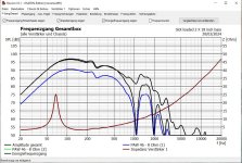
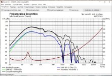
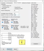
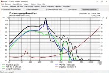
having said that here my suggestion of a change of your so called PPSL construction to get a more "horny" behaviour
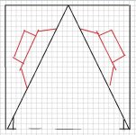
hope it helps, Stefano
P.S.: take your time and search for a Klipsch La Scala enclosure with bass reflex extension, this thing will work for sure with a horn cutoff < 340 Hz, with your 4 bass chassis you can build 4 of them and play around with the collocation of the 4 La Scala enclosures
Last edited:
for reference here my assumption what your so called PPSL looks like
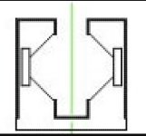
here a first hint for the la scala search
https://www.lautsprechermanufaktur-heyder.de/unsere-produkte/lmh-classics/die-la-scala
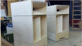
there is a scale in construction plan around for a 12 inch bass, so it should be possible to design something like a scale out 18 inch La Scala enclosure
looking closer at the construction video please note that the la scala has a closed box behind the driver and a slot load in front of the driver and a folded horn in front of the slot
if you need more sub bass extension in the 35 - 70 Hz octave you need the bassreflex extension, otherwise below 60 Hz no SPL with the La Scala original construction plan

here a first hint for the la scala search
https://www.lautsprechermanufaktur-heyder.de/unsere-produkte/lmh-classics/die-la-scala

there is a scale in construction plan around for a 12 inch bass, so it should be possible to design something like a scale out 18 inch La Scala enclosure
looking closer at the construction video please note that the la scala has a closed box behind the driver and a slot load in front of the driver and a folded horn in front of the slot
if you need more sub bass extension in the 35 - 70 Hz octave you need the bassreflex extension, otherwise below 60 Hz no SPL with the La Scala original construction plan
Last edited:
Hi @camplo,
i think i have found a better idea for the simulation of your PPSL enclosure
beside the coupling effect of the both chassis with a common bandpass reflex port that lowers the ground resonance a little bit
there is a chance to get a simulation with the enclosure divided symmetrically like this

the bandpass port frequency is estimated with this

The bandpass enclosure values are here

with the port calculation sheet i have assumed a quite large port with 60 X 15 cm
the value of the doubled port for the symmetrical double enclosure approach would be 60 X 30 cm
but i see that your slot is even smaller about 60 X 15 - 20 cm
so your bandpass port frequency is even lower!
even with the optimistic assumption you're screwed, see here why

your bandpass is too small, - 6 db Point is already at about 150 Hz
what really helps to verify this assumptions is a simple impedance measurement in your live construction, the values of the both impedance peaks tells a lot for a bandpass enclosure
the same for your mid high range horn - impedance graph tell us a lot already and you do not offer us a measurement of the room where the speaker is collocated
if you want to play around with BoxSim, here the download link
https://www.visaton.de/downloads/BoxSim_2-0_EN.zip
hope again it helps to sort out all the confusion, Stefano
i think i have found a better idea for the simulation of your PPSL enclosure
beside the coupling effect of the both chassis with a common bandpass reflex port that lowers the ground resonance a little bit
there is a chance to get a simulation with the enclosure divided symmetrically like this
the bandpass port frequency is estimated with this
The bandpass enclosure values are here
with the port calculation sheet i have assumed a quite large port with 60 X 15 cm
the value of the doubled port for the symmetrical double enclosure approach would be 60 X 30 cm
but i see that your slot is even smaller about 60 X 15 - 20 cm
so your bandpass port frequency is even lower!
even with the optimistic assumption you're screwed, see here why
your bandpass is too small, - 6 db Point is already at about 150 Hz
what really helps to verify this assumptions is a simple impedance measurement in your live construction, the values of the both impedance peaks tells a lot for a bandpass enclosure
the same for your mid high range horn - impedance graph tell us a lot already and you do not offer us a measurement of the room where the speaker is collocated
if you want to play around with BoxSim, here the download link
https://www.visaton.de/downloads/BoxSim_2-0_EN.zip
hope again it helps to sort out all the confusion, Stefano
Last edited:
- Home
- Loudspeakers
- Multi-Way
- Is it possible to cover the whole spectrum, high SPL, low distortion with a 2-way?