I am no expert on horns but I remember that some rule of thumb repeated on forums is that mouth circumference should be 1wl, which means for 100Hz ~340cm so roughly 1m x 1m (~40") square should work?
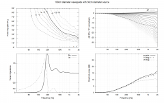
edit. Quick test ATH, 100cm diameter waveguide for ~15" driver and it looks like bigger is needed. In comparison ~cardioid system would be miniscule. But again trade-off is in the SPL capability for bass.
edit. Quick test ATH, 100cm diameter waveguide for ~15" driver and it looks like bigger is needed. In comparison ~cardioid system would be miniscule. But again trade-off is in the SPL capability for bass.
Attachments
Last edited:

Does a dual woofer slot load, like mine, make a difference?

Can I add the resistive slots to the wall behind the woofer?
Can I add the resistive slots to the wall behind the woofer?
I've got no idea, probably. I haven't even figured out what the heck the resistance and resistive slots are all about. I've been thinking the system as acoustic low pass filter, volume and aperture 😀 Damping material being there to reduce resonance. Your box has great volume so the aperture needs to be small I think. If you are fine perhaps destroying the box then start drilling and measure. Not sure how easy it is to verify the pattern, take weekend off and do it all outside live. Drill few holes and measure polars, rinse and repeat, until good pattern 🙂 Big speakers are pain to manufacture and measure, best of luck with it!
I think what will be some kind of issue here is that there is going to be quite a lot of volume displacement on high SPL, and holes relatively small with good pattern, so you'd probably need to resort some exotic materials for damping, or at least constrain the damping material inside some metal mesh or something, in order to keep it blowing out from the box, or flap around and add distortion. So practical issues mostly, you'd reach some suitable pattern eventually.
What I'd do I would make another prototype frame and test it dipole first. If you like it then start fiddling around with cardioid box, make it as small as possible and make multiple holes totalling about 1Sd, and then block some of them until good pattern.
Last edited:
I was thinking about it....the amount of damping material will cause pressure to make out of the enclosure faster/slower, I think...I think the tuning of the damping material has to do with matching the impulse with the inverse impulse, in the time domain. Just a guess.I've got no idea, probably. I haven't even figured out what the heck the resistance and resistive slots are all about.
Active cardioid directivity pattern formation is based on cancellation, just like passive. What I'm not sure of, is if having backside active unit gives any better efficiency than using single unit's backwave for cancellation. Guys a t Genelec do know this better - https://www.genelec.com/w371a
^^ Yes delay is the trick. Dipole has no delay on either side and destructive interference happens towards 90 deg off-axis. When the other side is delayed then the null angle turns, quite simple. How to manipulate delay passively, using single sound source, both sides of a woofer? Lets run it through:
Few things
1. affect path length between the sides, front and back
2. add group delay with acoustic low pass filter
3. add delay with some material that has slower speed of sound than air
4. something else I don't know of? the magical resistance?😀
Destructive interference happens best when both interfering sounds equally loud. If either is quieter the other dominates and attenuation is reduced. There is then a trade-off how much one can make delay with damping material before attenuation is too great and pattern not as good as hoped (low DI). "Problem" with damping material is that besides adding delay it also attenuates, and attenuation depends on absorption coefficients of the material and incident angle of the sound. As frequency dependent filter it creates some group delay as well.
Hence, all three must be balanced, path length between the sources (position of aperture), minimal damping material to prevent too much attenuation (close to dipole now!) and then manipulate acoustic low pass on the back side to start turning the pattern.
To have as much bass available as possible you'd need path length to be tens of centimeters (like with dipole).
Here is example, with sensible 50cm path length between front and back sound we get elevated DI for bass without losing too much lows.

Then, turn the nulls to higher angles adding delay to the backside somehow. Now we just use a delay block, easy!🙂


Shorter than path length delay we get ~supercardioidish pattern and delay equal to path length we get the cardioid. Too much delay and it turns to subcardioid and eventually the pattern disappears.
Such delay block is not possible passively/acoustically, so lets add some attenuation to it assuming we have material that does the delay and adds some attenuation. As mentioned earlier materials tend to have varying attenuation with frequency, very little on low frequencies. Not sure if there is materials available that add delay without attenuation. Perhaps some maze / metamaterial is possible. Anyway, the pattern gets poorer with attenuation to one side so it is better to avoid attenuation (on low frequencies) if at all possible. Except for possible reflections of short wavelengths, so logically we'd use some damping material but not too much.

What if the delay was made with group delay instead? Seems to work.

In reality we probably have some delay and attrnuation from damping material and some low pass due to volume inside the box and apertures:

Wow, looks good. Issue is that how to actually manufacture such thing, is it even possible? How to get 2nd order acoustic low pass for example? Well, use reflex box calculator and tune the resonance somewhere above the low pass on the emulation. Cool, how about the small delay and attenution? Just try few different materials and use what seems to work best. Also, as this is just idealized emulation simulation expect some additional variables that need to be tuned after the fact. So, some prototyping ahead.
There is also kind of secondary effect at play, path length around the box which makes supercardioidish pattern, for small bandwidth and with monopole boxes as well, but this is quite much higher in frequency, above 100Hz for sensible box sizes.
Few things
1. affect path length between the sides, front and back
2. add group delay with acoustic low pass filter
3. add delay with some material that has slower speed of sound than air
4. something else I don't know of? the magical resistance?😀
Destructive interference happens best when both interfering sounds equally loud. If either is quieter the other dominates and attenuation is reduced. There is then a trade-off how much one can make delay with damping material before attenuation is too great and pattern not as good as hoped (low DI). "Problem" with damping material is that besides adding delay it also attenuates, and attenuation depends on absorption coefficients of the material and incident angle of the sound. As frequency dependent filter it creates some group delay as well.
Hence, all three must be balanced, path length between the sources (position of aperture), minimal damping material to prevent too much attenuation (close to dipole now!) and then manipulate acoustic low pass on the back side to start turning the pattern.
To have as much bass available as possible you'd need path length to be tens of centimeters (like with dipole).
Here is example, with sensible 50cm path length between front and back sound we get elevated DI for bass without losing too much lows.
Then, turn the nulls to higher angles adding delay to the backside somehow. Now we just use a delay block, easy!🙂
Shorter than path length delay we get ~supercardioidish pattern and delay equal to path length we get the cardioid. Too much delay and it turns to subcardioid and eventually the pattern disappears.
Such delay block is not possible passively/acoustically, so lets add some attenuation to it assuming we have material that does the delay and adds some attenuation. As mentioned earlier materials tend to have varying attenuation with frequency, very little on low frequencies. Not sure if there is materials available that add delay without attenuation. Perhaps some maze / metamaterial is possible. Anyway, the pattern gets poorer with attenuation to one side so it is better to avoid attenuation (on low frequencies) if at all possible. Except for possible reflections of short wavelengths, so logically we'd use some damping material but not too much.
What if the delay was made with group delay instead? Seems to work.
In reality we probably have some delay and attrnuation from damping material and some low pass due to volume inside the box and apertures:
Wow, looks good. Issue is that how to actually manufacture such thing, is it even possible? How to get 2nd order acoustic low pass for example? Well, use reflex box calculator and tune the resonance somewhere above the low pass on the emulation. Cool, how about the small delay and attenution? Just try few different materials and use what seems to work best. Also, as this is just idealized emulation simulation expect some additional variables that need to be tuned after the fact. So, some prototyping ahead.
There is also kind of secondary effect at play, path length around the box which makes supercardioidish pattern, for small bandwidth and with monopole boxes as well, but this is quite much higher in frequency, above 100Hz for sensible box sizes.
Last edited:
Still digesting some things talked about above but first Q that came to mind, is...... Would I put the cancellation woofers on the sides of on the rear? Which is best rather, or does it affect the end result...I think above you are speaker about Front and rear sources.
Another thought, If one built an active cardioid system thoughtfully, it could be used successfully as cardioid, or just an enclosure with accompanying woofers. Flexibility.
Another thought, If one built an active cardioid system thoughtfully, it could be used successfully as cardioid, or just an enclosure with accompanying woofers. Flexibility.
@camplo check out this thread: https://www.diyaudio.com/community/threads/2-way-waveguide-cardioid-like.192737/ as it basically was the prototype for the Dutch & Dutch speaker. A passive solution but probably inspiring enough to give it a read.
^^ Above is simulation with active parts so rear driver with flipped polarity 50cm further away. The simulation is ment to emulate passive system though, rear driver with flipped polarity represents sound from backside of the cone and the delay and filter blocks represent damping material and effect of the box volume and aperture size, which is an acoustic low pass filter, all of which affect the sound of from backside of the cone.
Its simplified example, with two ideal point sources and no bafflestep or anything so wouldn't quite represent reality like that. It is an example how to use imagination accompanied with the simulation, what a passive cardioid system roughly consists of and the various blocks are tuned in order to gauge "what would happen if" and use reasoning how to make it happen in reality. Its a method how to make emulation to help coming up with a passive cardioid solution.
You could implement it actively just like in simulator, rear driver on a 50cm deep box, flip polarity and add delay and low pass filter and bam, ready. Or what ever you come up with on the simulator specific to your application. Better check it with baffle diffraction and all. No need to use imagination if going active.
Last edited:
I don't give much credence to subjective listening tests - unless they are done correctly, which is very difficult. I base my designs on good measurements and learned how to "read" those. This approach has never led me wrong, so I stick to it.Are you akin to hearing this error? I mean do you look at the chart and can easily imagine how this polar would sound, in effect.
But I have no doubts that the aberrations noted above would be audible. Proving that would be very difficult, so I let the measurements be my guide.
With an active cardioid setup, one could electrically change the system from cardioid to monopole at LFs thus reducing the excursion requirements on the woofers. Passive can't do that.
Hmm... I was studying my FR at listening point. I think I'm close to the worst listening and placement in the room, somewhat offcenter but not far away... I've a huge null at 30hz and another around 70hz (not looking at computer, right now)...
I'd like to think that cardioid will help me get a FR lacking these nulls regardless of such bad placement
Would I want to try additional woofers on the sides, the rear or both? The more the merrier I would think?
If all the sources were acoustically identical, I would think that they would be the most efficient at creating the cardioid affect, along with proper placement on the enclosure...
For large woofers I can see how this is an issue. As for the issue of dynamics, I will be subject to the same physics as anyone else... meaning that, at the day, a large cardiod system will be as dynamic as any other cardioid system of similar size or small.
Can I keep the ppsl and divide cabinet space to add woofers on the sides?
My guess is the closer the cancellation woofers are to the main woofers, the more effective???
Last edited:
Active cardiod is probably the hottest thing in studio monitor design since the launch of the Kii Three.Active Cardioid is something I have not seen a lot of..... at least above 200hz or so, where excursion is small for most large drivers, even in a small sealed cab if not sealed back woofer, it would seem that this would be an ideal solution. If trying to reach sub range, efficiency would be an issue....I am imagining a large box with stacked 18's on the front and sides...and rear? Does cardioid ruin room gain? Is the corner an issue? No more corner loading?
It works (near the front wall), but it eats up efficiency and amp. power.
Last edited:
Danley:
"The price you pay for the directionality is more subs! With a cardioid array, some of the subs are facing forward, i.e. towards the audience, and some are facing towards the rear, or away from the audience. The rear facing subs are used to provide cancelation thereby creating the familiar cardioid coverage pattern. The advantage to a cardioid array is more rear rejection. The major disadvantage is that the rear firing boxes do not contribute at all to the sound covering the audience. The end-fire system points all the subs towards the audience, but places them in a line, one behind the other like train cars. Spacing of the boxes is critical as it the application of delay to the boxes. The advantage to an end-fire system is higher efficiency as al the boxes contribute to the audience sound. The disadvantages are that the array will likely require lots of room, and the spacing of the boxes is critical."


I've experienced several variations of indoor end-fire (cardioid) subwoofer arrays, with various outcomes.
They had one thing in common: they were no match for simple (mostly Funktion One/Void) stacked frontloaded horn subs in terms of perceived quality/purity.
"The price you pay for the directionality is more subs! With a cardioid array, some of the subs are facing forward, i.e. towards the audience, and some are facing towards the rear, or away from the audience. The rear facing subs are used to provide cancelation thereby creating the familiar cardioid coverage pattern. The advantage to a cardioid array is more rear rejection. The major disadvantage is that the rear firing boxes do not contribute at all to the sound covering the audience. The end-fire system points all the subs towards the audience, but places them in a line, one behind the other like train cars. Spacing of the boxes is critical as it the application of delay to the boxes. The advantage to an end-fire system is higher efficiency as al the boxes contribute to the audience sound. The disadvantages are that the array will likely require lots of room, and the spacing of the boxes is critical."
I've experienced several variations of indoor end-fire (cardioid) subwoofer arrays, with various outcomes.
They had one thing in common: they were no match for simple (mostly Funktion One/Void) stacked frontloaded horn subs in terms of perceived quality/purity.
Attachments
Last edited:
That ol, new, friend of mine, Headroom. I've been imagining 4 18"s, two sets of ppsl stacked under the horn.... but then I'd be opt to try passive cardioid, and be "stuck" with the resulting headroom. It might be "enough"....
I like what @gedlee said about "mixed polar" filtering, the idea of possible having the additional woofer be cardioid and monopole at the same time....How would one even do this? GD?
A null eats headroom for lunch... what does a null mean to cardioid? Does Cardioid really narrow the beam width that much that its a sort of silver bullet??? Antinode eater?
Am I correct that cancellation on the side baffle is better than rear? Or is there any reason to favor cancellation in the rear? In the regards to cardioid performance I mean. Is there something special about the rear that makes more desirable to place cardioid woofer there? The closer the drivers the easier it is to use them in monopole is what I think.

Hornresp does Ripole now..... and aperiodic bi chamber... nice. I don't think I can explorer Cardioid with Horn resp just yet. So I am in VirtuixCad
@tmuikku I understand how to create the baffle in Vituixcad. I think that when multiple baffles are designed, they see each other acoustically in the simulation as system....I think....I how do I had the side baffles where there is no woofer?
I like what @gedlee said about "mixed polar" filtering, the idea of possible having the additional woofer be cardioid and monopole at the same time....How would one even do this? GD?
A null eats headroom for lunch... what does a null mean to cardioid? Does Cardioid really narrow the beam width that much that its a sort of silver bullet??? Antinode eater?
Am I correct that cancellation on the side baffle is better than rear? Or is there any reason to favor cancellation in the rear? In the regards to cardioid performance I mean. Is there something special about the rear that makes more desirable to place cardioid woofer there? The closer the drivers the easier it is to use them in monopole is what I think.
Huge boxes don't need round overs, Unless they are narrow. I have really wide ones, 32", at that width a round over is not needed because the wavelength is big.without hard to manufacture huge box with huge roundovers
I have large drivers in a two way. Theres a guy on FB with dual 21"s in an open baffle dipole, in a two way. I guess the open baffle creates the need for more headroom2 octaves before penalty on bass requires huge drivers so its not particularly suitable for a two way system.
Hornresp does Ripole now..... and aperiodic bi chamber... nice. I don't think I can explorer Cardioid with Horn resp just yet. So I am in VirtuixCad
@tmuikku I understand how to create the baffle in Vituixcad. I think that when multiple baffles are designed, they see each other acoustically in the simulation as system....I think....I how do I had the side baffles where there is no woofer?
Study that I did many years ago shows that monopole dipole and cardioid all have similar effects on the rooms modal characteristics at LFs. None of them is significantly better than the other in this regard. What does work is multiple subs spread around the room, after which the type of sub (monopole, dipole, cardioid) becomes irrelevant.I'd like to think that cardioid will help me get a FR lacking these nulls regardless of such bad placement
Would I want to try additional woofers on the sides, the rear or both? The more the merrier I would think?
It's not too hard to see how to do this.I like what @gedlee said about "mixed polar" filtering, the idea of possible having the additional woofer be cardioid and monopole at the same time....How would one even do this? GD?
Consider that all radiation patterns are the sum of radiation modes like monopole, dipole, quadrupole, etc. At LFs only the first two are relevant. At HFs dozens, even hundreds can contribute.
A cardio is the equal sum of a monopole and a dipole. Hyper-cardiod is a non-equal sum. AT the lowest frequencies we want a monopole hence two independent woofers (sealed independent enclosures) facing back to back will be in-phase. As the frequency goes up the phase has to change from 0 to 180 at which point they will be a cardioid. The amplitudes have to change as well to keep the system flat however. All this can be worked out into a DSP filter to achieve the end goal (although I have never done it myself except to show how to do a cardioid sub in my book.)
But the HFs will still diffract off of a sharp edge.Huge boxes don't need round overs, Unless they are narrow. I have really wide ones, 32", at that width a round over is not needed because the wavelength is big.
Theres a guy on FB with dual 21"s in an open baffle dipole, in a two way. I guess the open baffle creates the need for more headroom
View attachment 1134221
Community Multicells with "mumps". I'd like to polars of these.
This would seem true except if the placement were symmetrical, it seems the subs have to be directly in the corners or perhaps close to it, otherwise theres not enough modal variation to really sell the effect... is that correct?What does work is multiple subs spread around the room
I can't rotate a driver 180 while using the baffle tool generated response. I've figured that when I create a baffle response set its not producing measurements all the way to180 any more....I never changed a setting so I don't know where to lool.Better check it with baffle diffraction and all.
- Home
- Loudspeakers
- Multi-Way
- Is it possible to cover the whole spectrum, high SPL, low distortion with a 2-way?