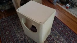
My driver baffle for the 15" is ~1.5" in depth and the wal's are 3/4"....whats the biggest radius I should use? I planned on purchasing a 1" radius tool for the router.
There are 2" 1/4 rounds that nest 3/4 panels. They work very well.
Rob 🙂
Attachments
Right now my issues is that the only 1.5r x 1/4" shank router bits are in China...sorta worried.
Buy the big 1/4 rounds. Even if you get a big round-over bit you will destroy your router routing a 1.5" 1/4 round unless you have a beast of a router.
That size bit should be on a 1/2" shaft min. The runout on a 1/4" shaft has to be pretty large. A quality bit that size is going to cost. For a one off deal you'd be wise to consider the 1/4 rounds available like Robh3606 posted.
And used in a table to make the operation safer. Swinging a bit that size from a 1/4" router free hand is at best difficult and prone to error.That size bit should be on a 1/2" shaft min.
OK I may have confused baffle step...I was taking 13550 and dividing it by the width...
AS long as this formula works
380/2.666ft (32")
= 142.53563390847711927982hz
false alarm....right?....the wavelength is so large by then....should I even do a 3/4"r?
AS long as this formula works
f3 = 115 / WB (where WB is the baffle width in meters)
f3 = 380 / WB (where WB is the baffle width in feet)
380/2.666ft (32")
= 142.53563390847711927982hz
false alarm....right?....the wavelength is so large by then....should I even do a 3/4"r?
Last edited:
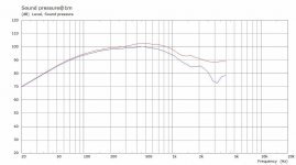
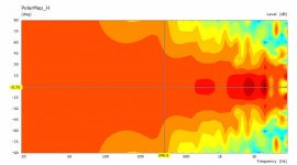
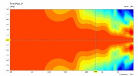
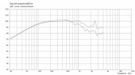
If you are trying to work out whether a roundover will affect diffraction lower in frequency then these simulations might help. They are of a 15" woofer in a baffle with a sharp edge vs one with a 36mm roundover.
As you see at around 500Hz the roundover starts to make a difference, below that no real difference.
As you see at around 500Hz the roundover starts to make a difference, below that no real difference.
Attachments
Last edited:
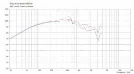
fluid, I understand the ragged response around 700hz ... also upsetting the response a bit below due to the baffle width ... but I'm confused by the ragged response that continues above 1.1khz when the 15" should be beaming. Seems to me the ragged response should be confined in the range of baffle width (in wavelength) upward to piston diameter (in wavelength). Beyond that frequency, the wavelength shouldn't even "see" the baffle as much as that sim shows.
Is the sim not taking into account the pistonic nature of the source?
Is the sim not taking into account the pistonic nature of the source?
Last edited:
Rockboard 40/60/80 doesn't crumble. Had a hard time finding some(in a reasonable time frame) recently so going with Comfortboard 80 from Lowes. 8lb/cuft density same as Rockboard 80
Yes,it would crumble for speaker stuffing. I was thinking about room treatments. Bad comment by me🙄
If box volume combined with rockboard stuffing amount is determined with a test box, wondering if adding rockboard during the construction stage is worth considering!
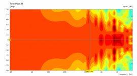
Yes it is, the polars are attached below, you can see the narrowing of directivity as frequency rises. Certainly as frequency rises the absolute accuracy of the model gets lower (due to the depth of the cone in this example). The only thing different between the two simulations if the baffle edge treatment.Is the sim not taking into account the pistonic nature of the source?
I didn't make observation fields for these simulations but they would probably be useful for visualising what is happening at different frequencies.
Attachments
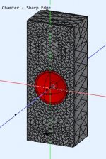
I would have to make a new CAD drawing for that, which I can do. The issue becomes making sure there is enough resolution in the mesh to accurately define the differences between a straight chamfer or a roundover or they end up looking quite similar when meshed.looks like an advanced software, how about simulation for a beveled edge vs the round over?
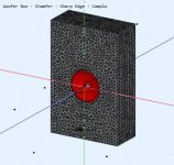
I ran some simulations on the mounting of the woofer in the baffle of the difference between flush, stepped, chamfer and roundover. There is a gif in the attachments which helps to see the difference. There is also an explanation of why the cone simulation accuracy drops off over 1K or so.
2 way waveguide speaker build ABEC modelling
Yes it is, the polars are attached below,
Wonderful example. Thanks!
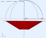
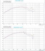
It is practically impossible to mount a conventional large driver flush in the way that the simulation shows, so you would have to treat that as an idealised example. I have not seen a driver of that size where there isn't a lip on the outside. I was trying to simulate that lip with the step which is why it is 13mm, as it matches the driver I was trying to model. You can see the step wreaks havoc on the response so rear mounting the woofer with either a chamfer or roundover in front is a good way to get around it.Mounting the driver flush takes away from edge diffraction that potently?
This is the side view of the Diaphragm as modelled, any sudden discontinuity at the surround junction creates quite a lot of diffraction.
You're very welcome. The more simulations I run the more I find myself coming to the conclusion that Earl Geddes was right again 😉Wonderful example. Thanks!
Attachments
Very informative thanks Fluid!
I see your first baffle shows a width of ~19"....my baffle is 32" wide...so this diffraction starts in lower for me correct?
I see your first baffle shows a width of ~19"....my baffle is 32" wide...so this diffraction starts in lower for me correct?
- Home
- Loudspeakers
- Multi-Way
- Is it possible to cover the whole spectrum, high SPL, low distortion with a 2-way?