If you run a wavefront sim of that I bet the left side is closed...the waves bounce off of the wall and return to the driver. How can it show you a true combined response without the output of the front of the driver actually leaving the cabinet? Depending on how close to that wall i bet the response changes. I'm probably not understanding something but, thats what I see.
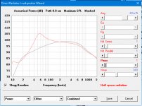
yours is my first sim of a TL. I entered your data, went into the loudspeaker wizard horn screen, slid the L12 to get the smoothest response (84cm), then went to the filling screen, set Fr to 4000, add filling starting in the driver end to smooth out the ripples. Too much damping and I had what looked like a sealed response, just the right amount and I had a vented response without nasty pipe resonances and just a little bit of ripple in the passband. I then lengthened the horn to extend the passband lower and re-optimized.
But it was already too large for me. Nevertheless, I see the benefits of a TL - damping pipe resonances without killing the response. But with an AXI driver you have the opportunity crossing low enough so that the pipe resonance of a bass reflex won't be a problem, depending of course on how loud you want to be able to play without chuffing...
Sliding L12 changes the length of the tube in front of the driver....how does this make sense? Or is the driver buried in the transmission line in some configurations?
L12 is the length of the first segment of the horn. By convention, the driver is mounted at S2 on an OD horn or at S2 of an OD1 horn. Changing L12 changes the distance from the left hand end of the TL to the center of the driver. Look at the schematic window while sliding L12 and you will see.
That doesn’t explain why during wave front sim there’s a boundary on the left side of the driver, this driver keeps the waves from exit the enclosure. How is that ok for the response?
OK, now what you posted makes sense in a weird sort of way, but had you studied pipe resonance theory before tackling a design like I recommended awhile back............
Resonances of open air columns
From this we see that in moving the driver we're not blocking anything, just shifting its rear output WRT the pipe's even, odd harmonics at the terminus where it sums with the driver's forward output in room and that we want it located at an odd harmonic, which to the first approximation is normally chosen based on taper ratio, though for a narrow BW sub is usually at its 5th harmonic [anywhere between on end to L*0.21] for max pipe gain with the trade-off that it will have max 'ripple' in its response, so normally limited to its 3rd harmonic dip ~ 2 octaves away.
GM
Last edited:
In the sim, the wavefronts exit the line on the right and expand into the room
The wavefronts that exit to the left of the driver never make it to the room but bounce back in forth from the boundary of the Tm and the driver
is this supposed to be that way, yes or no.....
The wavefronts that exit to the left of the driver never make it to the room but bounce back in forth from the boundary of the Tm and the driver
is this supposed to be that way, yes or no.....
No.
It is important to understand that the driver is represented by the red dotted circle, not by the red dotted straight line which simply indicates the position of the S2 cross-sectional area. Imagine when looking at the schematic diagram that the front side of the circular diaphragm (the red dotted circle) is facing you, and that it is directly radiating out of the screen towards you. The sound energy from the rear side of the diaphragm propagates back into the screen, to both the left (towards the closed end at S1 if the driver is offset, as is the case here) and also to the right (down the damped transmission line towards the open mouth at S3).
Rest assured, the Hornresp transmission line simulation calculations are done correctly, and the absorbent filling material model used is very accurate indeed 🙂.
I had my suspicions, thank you for clarifying, I’ll have to play with it more now that I understand better what I see. I was clearly confused, so thank you all 🙂
By convention, the driver is mounted at S2 on an OD horn or at S2 of an OD1 horn.
Just to clarify, the driver is mounted at S3 in an OD1 system.
I thought you were right 😕I had my suspicions, thank you for clarifying, I’ll have to play with it more now that I understand better what I see. I was clearly confused, so thank you all 🙂
TL introduces mass loading to the cone...I don't know where's the transition from TL to ML-TL, but surely any acoustic load reflects what happens behind the cone.
Just to clarify, the driver is mounted at S3 in an OD1 system.
I'm too used to starting at zero
I'm too used to starting at zero
🙂.
Traditionally the cross-sectional area at the throat end of a multiple-segment horn is designated as S1.
I know. It's the rest of the math and programming worlds that are different... Including Europe for numbering floors 🙂
If the frequency response is correct, that’s what matters, the thing that makes no sense is that sound is only emitted from one source when there should be two in the wavefront sim. If you draw a Tm using your mouse, in the wavefront sim, everything looks correct, but now you can’t sim freq response. So within the loudspeaker wizard the driver is facing directly at the screen...in the wavefront editor the driver can only face up down left or right. That’s what’s being suggested.
I ran the sims for bass reflex on horn resp and got different results, wonder which one to trust. With horn resp, the displacement increases drastically above about 40hz, where as with winisd displacement decreases above 40hz ion the same manner.....I'm thinking winisd is right.
I ran the sims for bass reflex on horn resp and got different results, wonder which one to trust. With horn resp, the displacement increases drastically above about 40hz, where as with winisd displacement decreases above 40hz ion the same manner.....I'm thinking winisd is right.
I am pretty sure that you can trust Hornresp... 🙂.
- Home
- Loudspeakers
- Multi-Way
- Is it possible to cover the whole spectrum, high SPL, low distortion with a 2-way?