A link please 🙂 (or links in this case)our blog post had measurement data validating the theory. It has also been independently verified by Rasmus in the FB DIY loudspeaker project PAD group. Not sure what you miss?
Last edited:

No, I haven't used FB in like 5 years or so.
BUT, I went down the rabbit hole.
Would be nice not to send someone into the woods.
(seems to be a not so nice trend these days 🙁 )
https://www.facebook.com/groups/DIYLoudspeakerProjecPad/permalink/1618301571859007
I am gonna quote it here as a backup for everyone.
Full copyrights to original poster obviously
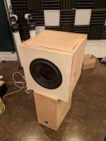
Woofer: Dayton Audio RSS315HF-4
One applied with passive notch, after EQ corrected actively to get similar freq resp.
BUT, I went down the rabbit hole.
Would be nice not to send someone into the woods.
(seems to be a not so nice trend these days 🙁 )
https://www.facebook.com/groups/DIYLoudspeakerProjecPad/permalink/1618301571859007
I am gonna quote it here as a backup for everyone.
Full copyrights to original poster obviously
Woofer: Dayton Audio RSS315HF-4
One applied with passive notch, after EQ corrected actively to get similar freq resp.
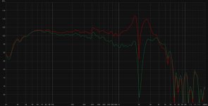
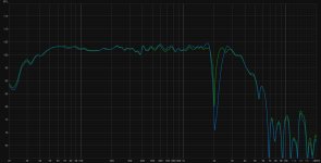
After starting to look at how passive notch filters can reduce harmonic distortion at subharmonic frequencies below cone breakup peaks in active setups, I've been particularly interested in seeing what this new bag of tricks might do for the lovely set of Dayton RSS315HF-4 I have sitting idle in my shed. This is an excellent "hifi" subwoofer with a 12" aluminum cone and a low-distortion motor. However, it has a pair of very severe cone breakups at ~1765 Hz and ~2660 Hz with a sharp cancellation in between.
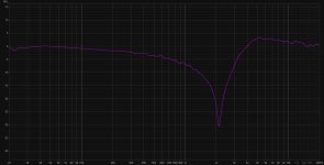
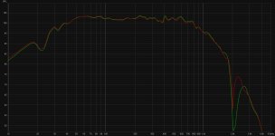
I spent some time investigating various filter configurations yesterday, but will just share the final one I settled on: I ended up with a single, fairly deep notch filter centered between the two breakup peaks, pulling both of them down by about 15 dB. The filter consists of a 1.5 mH air core inductor and a 3.63 uF capacitor (made from 3.3 and 0.33 plastic caps in parallel).
To simulate a somewhat realistic use case, I added an active 4th order (24 dB/octave) Linkwitz-Riley low-pass filter at 1000 Hz.
The resulting curves show a significant reduction of all higher order harmonic distortion components in the range between 200 Hz and 1000 Hz, especially at the subharmonics of the two breakup peaks. In effect, the passive notch makes this driver perfectly usable in the mid bass & lower midrange (assuming you match directivity), which is quite a feat in my mind.
Just listening to the driver running "full range" but EQ'd flat with and without the passive notch, the difference in clarity / distortion is striking.
[\quote]
Attachments
Also, I don't understand why some of you keep distortion in absolute numbers.
Which can be hard but mostly annoying to read, counting dB differences.....
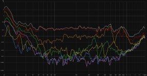
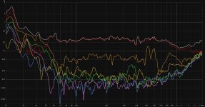
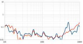
So here are the Purifi results given in percentages (can also to in relative dB).
I had to trace the curves, so there are some artifacts.
Also resolution in the lower dB region isn't great this way.
Blue = no passive filter and notch
Red/Orange = with passive filter and notch.
Which can be hard but mostly annoying to read, counting dB differences.....
So here are the Purifi results given in percentages (can also to in relative dB).
I had to trace the curves, so there are some artifacts.
Also resolution in the lower dB region isn't great this way.
Blue = no passive filter and notch
Red/Orange = with passive filter and notch.
Attachments
As none would listed to the speaker with the peak present, best would be to normalise the FR to flat and show the remaining distorsion. Anyways, the purify page shows that in absolute terms, the distortion is reduced approximately 10 dB with the serial notch.
//
//
That is still hard to compare when the freq resp goes down because of some filter or so.
In some cases it can be extremely deceiving.
Just show it relative, programs do that even automatically these days.
It's even a relative unit.
In some cases it can be extremely deceiving.
Just show it relative, programs do that even automatically these days.
It's even a relative unit.
Not really an "artifact". Think of it this way, the signal goes through a nonlinear transfer characteristic and out comes the distorted signal - harmonics, etc. Then this distorted signal passes through a filter which can accentuate or decrease the harmonics (and fundamental) as they pass through the peaks and dips in this secondary filter. The filter changes the harmonic and fundamental levels thus changing the %THD, but the harmonics haven't really changed after the nonlinearity, its the system FR that changed.So you're saying as well, that this is just a measuring artifact basically?
This reminds me of discussions about the (absence of the) need to damp the resonance of metal dome tweeters that are (way) above 20kHz.
A proper comparison would be to apply the passive notch AND eq the peak back actively to its original level. So much for Facebook?
A proper comparison would be to apply the passive notch AND eq the peak back actively to its original level. So much for Facebook?
Last edited:
Wouldn't it be fair to compare the passive notch to an active setup with EQ applied that has the same SPL reduction and Q as the notch?
Well it does make you thinking.This reminds me of discussions about the (absence of the) need to damp the resonance of metal dome tweeters that are (way) above 20kHz.
A proper comparison would be to apply the passive notch AND eq the peak back actively to its original level. So much for Facebook?
If this is indeed so effective, even for woofers one could filter down some issues and EQ it back again.
There are quite some (very) affordable woofers out there that besides these breakup resonances, doing very great.
But yeah, another one that comes to mind, is your typical alu dome 20-30kHz resonances with dome tweeters.
If I remember well, I have seen people doing that, but the THD didn't change.
just note that it’s only a certain type of motor distortion that we can attenuate by going to current drive (increased impedance in the amp-driver loop). for a tweeter this mechanism may not be dominant unlike for larger cone drivers so it may not show up in a measurement.
@lrisbo But isn't this just a mechanical resonance, not a motor resonance?
I guess what you mean is probably more like how the motor is able to absorb this resonance?
Aka, the self inductance of the motor or something. Although for tweeter that is pretty low to begin with.
Makes you wonder again if this method is not more effective with speakers with plenty of demodulation in the motor?
Since you basically just shorting the entire thing. (the RSS315HF also has plenty of demodulation going on).
I am still a bit confused about it, because I really think I have tried something similar in the past with a woofer break-up bit it didn't do anything at all.
Trying to dig trough my old measurements, but that is quite the pile.
edit: I guess the BL also has an effect on this as well, since it basically just amplifies more/less such signal back into the motor.
Attachments
Last edited:
The distortion reduction we get from a notch in series with the driver: the signal gets distorted by the motor and the distortion can be modelled as a back EMF signal (dynamically varying inductance from position dependent and hysteresis). For example, a 1kHz signal results in a 3kHz back EMF which results in a 3kHz current that gets transformed into driving force. If the notch filter increases the loop impedance at 3kHz we reduce the 3rd harmonic current which directly maps to reduced 3rd harmonic in the acoustic output (assuming this is dominant). If we have a mechanics/acoustical resonance at 3kHz we will se a distortion peak around 1kHz since the 3rd harmonic gets amplified by the resonances in the mechanical domain. The notch can then both EQ the response of the fundamental (dip the 3k current to force response) AND attempt by hate the harmonic at 3k generated by the 1k signal. This will thus flatten the distortion peak around 1k.
the BL ‘transformer’ is of course transmitting energy both ways. This is surely mapping distortion from the mechanical domain back to the electrical domain. however, this mechanism is predominant around fs where the velocity peaks and drops off fast with rising frequency as the driver gets into the mass controlled range. below fs, the distortion of the current can exceed the distortion of the acoustic output. reason: around fs the high electrical damping from the strong high BL motor acts as a motional servo which can suppress distortion from the suspension. This requires that the current is distorted to compensate.
Gets amplified by resonances? Sorry, I don't follow that.If we have a mechanics/acoustical resonance at 3kHz we will se a distortion peak around 1kHz since the 3rd harmonic gets amplified by the resonances in the mechanical domain.
In either case the peaks we are talking about, are always mechanical (cone) resonances?
So happening in the mechanical circuit.
Never electrical or acoustic resonances.
The BL at these frequencies is constant, we are (very) far from Fs (no BL(X) ), so I am a bit confused why you're mentioning it?
a mechanical/acoustic resonance can give a peak in the force to acoustic pressure transfer function. This ‘amplifies’ distortion products from the motor that shows up in the driving force
- Home
- Loudspeakers
- Multi-Way
- Is it possible to cover the whole spectrum, high SPL, low distortion with a 2-way?