It seems that RCA drivers are with phenolic diaphragm. I have a few Jensen drivers, and I find that phenolic sound very nice although the frequency response is... 16K would be impossible, but well, we all know vintage speaker's specification is always optimistic to some degree. 🙂
Right, well... first I have to admit, after reading the interview I couldn't escape the impression that Mr. Sides is a bit of a pompous bore.
In spite of his (?) accomplishments, he seems to be full of himself as he apparently can't resist emphasizing the greatness of all the things he does.
A little more modesty would do this man good.
This impression was confirmed after reading a comment on audioheritage by Steve Schell, who knew A.J. May - the designer of many RCA loudspeakers, personally.
Speaking of modesty:
"Mr. A.J. May died in early 2004. He was a sweet, kindly man, the sort you cannot help but like immediately. He designed the LC-9A, the MI-9462 (Ubangi) bass enclosure, the majority of RCA's postwar radial horn products, and much more. He was very humble though, always attempting to assign credit to others. He was John Volkmann's (inventor of the radial horn) understudy in the early years, and helped him to maintain an ever-changing experimental sound system at Radio City Music Hall. He also worked for a time at Princeton with Harry Olson. He frequently said "I was their chief measurer", preferring to be regarded as an assistant rather than the innovator he truly was. He told me in 2002, on the day the picture was taken: "It has been a very interesting life."
Last edited:
Comment:
"I couldn't help but think Mr. Sides has had a serious long-term RCA jones going on...
Not only the LC-9A 'clone' (HR2), but now this mini-Ubangi-vibe looking thing:
HR4 – OceanWay Audio
Makes me wonder if a turn on the spinorama would support the jibba-jabba."
Steve Schell:
"Almost every story that I have heard over the past twenty five years that mentioned RCA radial horn enclosures has involved Mr. Alan Sides in some way. As the story goes, he once had a storage facility under the Pacific Ocean Park pier in Venice, CA that had many of the MI-9462 double woofer "Ubangi" theatre bass bins stacked up. I am a bit miffed that in recent years he has chosen to market monitoring systems to recording studios that feature the radial horn technology while refusing to give credit to RCA and its engineers that made it all happen in the late 1940s to early 1950s. I can verify this as I am fortunate to have several boxes of vintage RCA documentation from the inventors of these radial horns and systems. I once had a long phone conversation with Mr. Sides and he seemed fully aware of the RCA contributions, which makes his continuing refusal to provide acknowledgement all the more perplexing."
"The story of the RCA LC-9A is an interesting one, at least to RCA buffs. This model was developed by Mr. A.J. May, who had a storied career in speaker engineering at RCA from 1943 until the early 1980s. It was RCA's attempt to compete with Altec's A7, and to improve on what RCA felt were the A7's shortcomings, most notably the lack of directivity control through the crossover region.
The LC-9A used 120 degree radial horn flares for both high and low frequency sections, and achieved a very uniform pattern over this angle. Due to the high construction costs of the cabinet and cast horn flares it was not cost competitive with the A7 and sold in very small numbers. RCA was really beginning to unravel by the time the LC-9A was introduced, and it is probably safe to say that it did not receive the marketing effort that the design deserved. I have heard a pair of them with original drivers, and they really are marvelous speakers with a captivating sound.
The LC-9A was a bass reflex design, with three large ports on the lower front faces of the cabinet. Mr. May had intended to fit passive radiators to these openings. As he told me the story, his managers heard the design at an early stage, found the performance to be "good enough", proclaimed the design finished, and reassigned A.J. to other tasks. Ah, the tribulations of working for a large corporation!
No one is certain how many LC-9As were built and sold, but it may have been only two or three hundred. The people I know who own them hold them in high esteem and wouldn't part with them for anything.
I've never heard the two speakers side by side. In fact I've only listened carefully to LC-9As once as a stereo pair. I would have to give the nod to the RCA though.
The bass sounds extremely smooth and punchy; this is characteristic of the radial horn combination cabinets, including the larger RCA theatre models. The high frequency performance is unique in my experience, though better suited to some situations than others. The radial horn has a 120 degree horizontal dispersion pattern, and this is not just on paper. I carefully listened on and off axis, and at 60 degrees off axis (virtually beside the cabinet) the highs sound nearly identical to the sound on axis- unbelievable! The highs and lows blend together very well both on and way off axis, a very different experience from the beamy highs of the A7. Of course I tend to get all wiggly in the presence of rare speakers, so my exhuberence should probably be factored in."
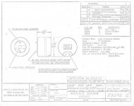
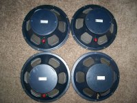
Here is JBL's sales model drawing for the LE175/MI-11419 small format driver they provided to RCA for the LC-9A (courtesy of Steve Schell), as well as images of the MI-11421 15" woofers:
The LC-9A used 120 degree radial horn flares for both high and low frequency sections, and achieved a very uniform pattern over this angle. Due to the high construction costs of the cabinet and cast horn flares it was not cost competitive with the A7 and sold in very small numbers. RCA was really beginning to unravel by the time the LC-9A was introduced, and it is probably safe to say that it did not receive the marketing effort that the design deserved. I have heard a pair of them with original drivers, and they really are marvelous speakers with a captivating sound.
The LC-9A was a bass reflex design, with three large ports on the lower front faces of the cabinet. Mr. May had intended to fit passive radiators to these openings. As he told me the story, his managers heard the design at an early stage, found the performance to be "good enough", proclaimed the design finished, and reassigned A.J. to other tasks. Ah, the tribulations of working for a large corporation!
No one is certain how many LC-9As were built and sold, but it may have been only two or three hundred. The people I know who own them hold them in high esteem and wouldn't part with them for anything.
I've never heard the two speakers side by side. In fact I've only listened carefully to LC-9As once as a stereo pair. I would have to give the nod to the RCA though.
The bass sounds extremely smooth and punchy; this is characteristic of the radial horn combination cabinets, including the larger RCA theatre models. The high frequency performance is unique in my experience, though better suited to some situations than others. The radial horn has a 120 degree horizontal dispersion pattern, and this is not just on paper. I carefully listened on and off axis, and at 60 degrees off axis (virtually beside the cabinet) the highs sound nearly identical to the sound on axis- unbelievable! The highs and lows blend together very well both on and way off axis, a very different experience from the beamy highs of the A7. Of course I tend to get all wiggly in the presence of rare speakers, so my exhuberence should probably be factored in."
Here is JBL's sales model drawing for the LE175/MI-11419 small format driver they provided to RCA for the LC-9A (courtesy of Steve Schell), as well as images of the MI-11421 15" woofers:
Attachments

Last edited:
I can't see one thing on the 70 year old leaflet that makes it unattractive.Wait a minute, the paper says 22000Hz!
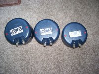
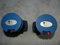
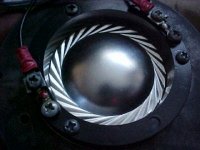
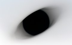
It seems that RCA drivers are with phenolic diaphragm 🙂
It's Aluminum (1st image shows the RCA diaphragm), like the diaphragm in the original JBL LE75 (shown in unusual blue coating and including the red wax seals that are also visible on the RCA drivers shown above).
Attachments
Last edited:
I can't see one thing on the 70 year old leaflet that makes it unattractive.
The leaflet is probably 10 years younger, but the horn technology was developed during the late 40s and early 50s.
Last edited:
Some background info on radial horns (by Bill Woods, Steve Schell ao.):
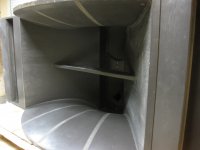
In a radial horn two sides are straight while the other two are curved. It is a hybrid horn design that combines the excellent directivity of the conical horn in the horizontal while achieving the low frequency loading of an exponential expansion with the curved sides. Keeping this exponential expansion in mind it can be seen that the straight sides expand so rapidly from the throat that the curved sides need to initially neck down in the vertical axis in order to maintain the desired overall exponential expansion of the cross section.
John Volkmann invented the radial horn in the 1930s, and A.J. May, who developed most of the RCA radial horn products, was his assistant and understudy after 1943. A.J. once explained Mr. Volkmann's rationale for the radial horn to me so elegantly and succinctly that I sorely wish that I had taped the conversation. He said something to the effect that the radial horn was designed to optimize the dispersion vs. frequency in the most important, i.e. horizontal axis, while sacrificing it in the less important vertical axis. The design utilized an exponential flare expansion to maximize the bandwidth of adequate loading for the driver in a given horn size.
A.J. also liked conical (straight sided) horns very much; he referred to them as "plane-sided." Straight horn walls do the best job of maintaining a given dispersion pattern over a wide frequency range, the angle being determined by the included angle between the walls in the axis of interest. A.J. built and tested (and tested, and tested...) a wide variety of experimental conical as well as radial horns in the late 1940s and early 1950s. He really liked the way that a conical horn could achieve any desired horizontal and vertical pattern by selecting the proper angles of the walls. RCA never produced conical horns from this work though, as A.J. found that they were too large physically for their useful bandwidth compared to the exponential horns. The relative lack of low frequency loading from the rapidly expanding throat section resulted in a horn with too little low end in a given size compared to an exponential horn. The radial horns were considered a good compromise between size and directivity, and were widely used by RCA and many other companies.
I am not sure why the LC-9 uses a curved profile on only one side of the bass horn, though I assume that A.J. achieved the desired expansion without further complicating an already difficult to build loudspeaker. Some of his other designs like the MI-9462 (Ubangi) bass cabinet have curved flares on two sides.
The radial horn also strikes me as elegant conceptually for another reason. The classic exponential horn is calculated on the expansion of a plane wave. We can assume that in the real world the wavefront will bulge outward in the center as it travels down the horn, as this is the nature of wavefronts that progress over an expanding area. This bulging will give the wavefront a greater surface area than a plane of the same exterior dimensions. If this is indeed the case then the horn actually expands too quickly for the calculated cutoff frequency. A radial horn is based on a lengthening radius from a hypothetical point where the straight sides would meet. Dividing the length of this arc at a given distance from the throat from the desired cross section at that point in the horn yields the vertical dimension needed to maintain the expansion. So, the radial exponential horn expands in a manner that maintains the correct wavefront area better than most exponential horns.
To achieve a smooth transition in a conical horn at the mouth it is generally expanded a second time, for about 10% of the horns length. In a conical radial horns this curve is only on the top and bottom plane of the horn, swept in an arc. The sidewalls remain flat. In this way, you are able to “squeeze” more energy at the desired directivity over a simple 4 planed horn of the same directivity pattern.
Questions:
The speed bump is the result of following an exponential flare profile. When you squeeze the horn into a radial horizontal format, the mathematical function forces this bump in the geometry.
AJ made many prototypes without the bump, as it appeared a smooth transition would work better. He was right. He told me a lot of work went to that LC9 horn.
Later Keele at JBL realized in his big polynomial radials, you could do the same thing.
Because of the smooth flare profile in the RCA horn, it is superior to the Altec design.
This horn can also be done in a conical radial format, as used in some Yorkville products.
Radial horns have a smoother response curve than other types of horns, but the phase is upset due to the twisting the air must do traverse the horn. There is nothing wrong with this as you get free EQ by the horn - they go out quite far in response with good output.
The Western Electric KS12025 and a Peavey horn made some time ago share these characteristics. It is interesting to note the WE horn used a 5/8” throat to control some of the “bump“ problems.
To expand a bit on the "speed bump", it results from maintaining an exponential expansion while having two straight walls that define the horizontal pattern. The throat section expands so quickly due to this that the vertical dimension has to neck down initially to maintain the exponential expansion.
In a radial horn two sides are straight while the other two are curved. It is a hybrid horn design that combines the excellent directivity of the conical horn in the horizontal while achieving the low frequency loading of an exponential expansion with the curved sides. Keeping this exponential expansion in mind it can be seen that the straight sides expand so rapidly from the throat that the curved sides need to initially neck down in the vertical axis in order to maintain the desired overall exponential expansion of the cross section.
John Volkmann invented the radial horn in the 1930s, and A.J. May, who developed most of the RCA radial horn products, was his assistant and understudy after 1943. A.J. once explained Mr. Volkmann's rationale for the radial horn to me so elegantly and succinctly that I sorely wish that I had taped the conversation. He said something to the effect that the radial horn was designed to optimize the dispersion vs. frequency in the most important, i.e. horizontal axis, while sacrificing it in the less important vertical axis. The design utilized an exponential flare expansion to maximize the bandwidth of adequate loading for the driver in a given horn size.
A.J. also liked conical (straight sided) horns very much; he referred to them as "plane-sided." Straight horn walls do the best job of maintaining a given dispersion pattern over a wide frequency range, the angle being determined by the included angle between the walls in the axis of interest. A.J. built and tested (and tested, and tested...) a wide variety of experimental conical as well as radial horns in the late 1940s and early 1950s. He really liked the way that a conical horn could achieve any desired horizontal and vertical pattern by selecting the proper angles of the walls. RCA never produced conical horns from this work though, as A.J. found that they were too large physically for their useful bandwidth compared to the exponential horns. The relative lack of low frequency loading from the rapidly expanding throat section resulted in a horn with too little low end in a given size compared to an exponential horn. The radial horns were considered a good compromise between size and directivity, and were widely used by RCA and many other companies.
I am not sure why the LC-9 uses a curved profile on only one side of the bass horn, though I assume that A.J. achieved the desired expansion without further complicating an already difficult to build loudspeaker. Some of his other designs like the MI-9462 (Ubangi) bass cabinet have curved flares on two sides.
The radial horn also strikes me as elegant conceptually for another reason. The classic exponential horn is calculated on the expansion of a plane wave. We can assume that in the real world the wavefront will bulge outward in the center as it travels down the horn, as this is the nature of wavefronts that progress over an expanding area. This bulging will give the wavefront a greater surface area than a plane of the same exterior dimensions. If this is indeed the case then the horn actually expands too quickly for the calculated cutoff frequency. A radial horn is based on a lengthening radius from a hypothetical point where the straight sides would meet. Dividing the length of this arc at a given distance from the throat from the desired cross section at that point in the horn yields the vertical dimension needed to maintain the expansion. So, the radial exponential horn expands in a manner that maintains the correct wavefront area better than most exponential horns.
To achieve a smooth transition in a conical horn at the mouth it is generally expanded a second time, for about 10% of the horns length. In a conical radial horns this curve is only on the top and bottom plane of the horn, swept in an arc. The sidewalls remain flat. In this way, you are able to “squeeze” more energy at the desired directivity over a simple 4 planed horn of the same directivity pattern.
Questions:
- Did either of you ever query A.J. May on his theory behind that elegant flowing throat section ? ( And why it was used on only 1/2 of one axis ? ).
- The initial throat portion reminds me of a real "smooth running" water weir or even an earthen berm. Not being a horn designer, I've wondered what the acoustic purpose was of that speed "bump". I know CD horns have throat constrictions engineered into them, but this restriction is so mild that I've had to wonder about it. Could you comment on that part of the design ?
The speed bump is the result of following an exponential flare profile. When you squeeze the horn into a radial horizontal format, the mathematical function forces this bump in the geometry.
AJ made many prototypes without the bump, as it appeared a smooth transition would work better. He was right. He told me a lot of work went to that LC9 horn.
Later Keele at JBL realized in his big polynomial radials, you could do the same thing.
Because of the smooth flare profile in the RCA horn, it is superior to the Altec design.
This horn can also be done in a conical radial format, as used in some Yorkville products.
Radial horns have a smoother response curve than other types of horns, but the phase is upset due to the twisting the air must do traverse the horn. There is nothing wrong with this as you get free EQ by the horn - they go out quite far in response with good output.
The Western Electric KS12025 and a Peavey horn made some time ago share these characteristics. It is interesting to note the WE horn used a 5/8” throat to control some of the “bump“ problems.
To expand a bit on the "speed bump", it results from maintaining an exponential expansion while having two straight walls that define the horizontal pattern. The throat section expands so quickly due to this that the vertical dimension has to neck down initially to maintain the exponential expansion.
Last edited:
Ironically, not necking down the vertical while maintaining the overall expansion can allow a more OSesqe horizontal, and a reduction in this effect in the vertical where it is less wanted, leading to a potentially closer to ideal cylindrical/spherical wavefront.the straight sides expand so rapidly from the throat that the curved sides need to initially neck down in the vertical axis in order to maintain the desired overall exponential expansion of the cross section.


Ironically, not necking down the vertical while maintaining the overall expansion can allow a more OSesqe horizontal, and a reduction in this effect in the vertical where it is less wanted, leading to a potentially closer to ideal cylindrical/spherical wavefront.
This has probably been done, but it does make sense indeed.
I was contemplating a Spherical Radial horn as well.
The "speed bumps" suddenly reminded me of the slot in 18Sound's XR waveguides.

Last edited:
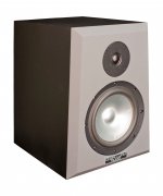
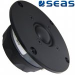
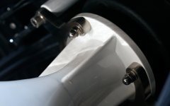
The tweeter is most probably to be SEAS Prestige 27TDC. Nothing fancy. 🙂
Well spotted!
Attachments
The radial type of horns are very interesting! I have incorporated an offset in my program to show the different profile transitions:

When fins are existent then the vertical profile begins to expand faster exactly at the end of the fins. The sum of the cross sectional area of all sections between the fins and the walls should give the desired surface expansion. At the end of the fins an only conical expansion would result. Therefore, the vertical profile expands from here. Leaving the fins changes the game considerably and the first flat vertical conical section looks more like a slot waveguide in order to form the wave front and not like a horn.
This example may not give proper results because of missing fins.
This has probably been done, but it does make sense indeed.
I was contemplating a Spherical Radial horn as well.
The "speed bumps" suddenly reminded me of the slot in 18Sound's XR waveguides.
When it comes to horn porn, that does it for me 😱
The radial type of horns are very interesting! I have incorporated an offset in my program to show the different profile transitions.
Impressive work, as usual!
I wonder what a horn with a golden ratio expansion would look like.
Possibly similar to Joseph Crowe's Exponential Spiral horns.
There are probably only a few people on this planet who are able to generate such horns in a strictly mathematical manner.
I can think of only 3 (including you) and it wouldn't surprise me if yours turn out to be mathematically the most elegant/puristic.
Last edited:
Thanks!
Writing the math on paper is one thing but programming is much more complicated.
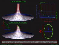
Did you mean real spiral functions? I have done the most interesting: hyperbolic, Sici, Cornu. Sprirals for horn profiles work very well! Don and I simulated them and all work properly. I personally liked the Sici profile most:

Writing the math on paper is one thing but programming is much more complicated.
Did you mean real spiral functions? I have done the most interesting: hyperbolic, Sici, Cornu. Sprirals for horn profiles work very well! Don and I simulated them and all work properly. I personally liked the Sici profile most:
When it comes to horn porn, that does it for me 😱
The slot looks like a vertically placed elliptical constriction of rougly 0.75 relative to the horn's entrance along the center line, thus allowing the wavefront to initially expand only in the vertical plane.
It's basically a smooth diffraction slot and these horns are supposed to sound very good, but don't load the driver very well below 800Hz.
Attachments
Last edited:
We might be better off splitting this vintage gear into its own thread. We seem to be getting pretty far OT.
Did you mean real spiral functions? I have done the most interesting: hyperbolic, Sici, Cornu. Sprirals for horn profiles work very well! Don and I simulated them and all work properly. I personally liked the Sici profile most:
Some documents for your inspiralation 😀
Attachments
-
Three_Spirals_1.pdf195.2 KB · Views: 92
-
Two Dimensional Spirals.pdf450.5 KB · Views: 125
-
Spiral Patterns in Shells & Horns.pdf831.4 KB · Views: 135
-
FRONT EXPONENTIAL AND SPIRAL HORNS (1).pdf434.1 KB · Views: 185
-
 golden-spiral6 (1).gif21.9 KB · Views: 117
 -
 file.jpg438.1 KB · Views: 108
 -
 kisspng-golden-triangle-golden-ratio-golden-spiral-logarit-5ae7ffb0e685b1.4498919515251537129442.jpg75.7 KB · Views: 121
Last edited:
- Home
- Loudspeakers
- Multi-Way
- Is it possible to cover the whole spectrum, high SPL, low distortion with a 2-way?