No expert, but FWIW, etc., extreme MLTL to me since two distinct pipes/ducts..........pipe resonances
Randy, you need to add some dampingm to really see but… doesn’t look great — attempt to get to low — to someone who mostly ignirs the undamped graphs.
List all the peaks — frequency and magnitude -- each represents a resonance. The spacing I believe in a reflex you will not see them. The relationship between the numbers tells a story.
We need an expert. @Scottmoose
As an example, this planset is essentially an exploration, with a reflex, a hybrid, an ML-TL (folded & unfolded), and a Voigt.
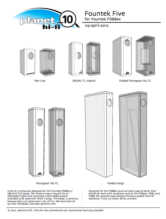
http://p10hifi.net/FAL/downloads/Fountek-Five-planset-030412.pdf
https://www.diyaudio.com/community/threads/the-fountek-five-for-fr88ex.210106/
dave
Thanks man, always
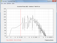
That wide slump over 40hz, is that a dead zone? Bad zone?
Winisd returns a strong flat result around that same area
Dave, you mentioned aspect being the difference between BR and TL and as everyone has picked up, the form factor is forcing two significant pipes to form
Guys
Could this be a case where the only way to beat the aspect ratio is not a port but maybe a PR or two on the face near the driver?
You decide on a frequency limit for the port resonance, and this means your port can't be longer than that. Like many speaker compromises you can let the resonance sit just outside this range.
When you make the port shorter, you'll have to make it narrower so it works at the same frequency. This increases the port velocity. You see whether you can get sufficient output at a low enough velocity that you don't get port chuffing.
If you can't make this work, you have to change something. A passive radiator is just one option.
Thanks for the suggestion. That shouldn't cause any probs in drawing something like that in if I can translate what HR and Winisd results to CAD. This is where I am stumblingIt looks like a pretty severe port for a bass reflex and I would double-check the velocity of air to see if you are going to get chuffing at the port at high excursion. Your last drawing shows a port at the front, perhaps you could consider a symmetric port on either side near the speaker to keep the symmetry? Like the drawing below...If you need room for the other drivers you could just move the ports back...just like you have on the right side of your drawing, only shorter.
View attachment 1257345
If my port is 60cm, xover at 200hz should keep all these resonances very down. Is this correct, am I getting it?No expert, but FWIW, etc., extreme MLTL to me since two distinct pipes/ducts..........pipe resonances
Dave, guys
This wide slump over 40hz, its down over 10db from the hump higher up. Is this a bad frequency response or am I not reading this right?
No such luck  , the pipe resonances are made by the cab's tuning, so while the XO is rolling off the high end, anytime the signal dips down enough to energize the vent it will 'sing' out of tune (comb filter) with whatever the speaker is playing at that point in time regardless of where it's coming from and why I always recommend damping any vent since this is potentially an audible problem whenever there's a pipe/tuning that extends its resonances > ~driver Fs and/or Fb.
The big dip indicates an under-damped alignment; it won't be that bad in reality, but there will be a sag in the response.
When using HR, please Export the file for us to Import, view.

, the pipe resonances are made by the cab's tuning, so while the XO is rolling off the high end, anytime the signal dips down enough to energize the vent it will 'sing' out of tune (comb filter) with whatever the speaker is playing at that point in time regardless of where it's coming from and why I always recommend damping any vent since this is potentially an audible problem whenever there's a pipe/tuning that extends its resonances > ~driver Fs and/or Fb.The big dip indicates an under-damped alignment; it won't be that bad in reality, but there will be a sag in the response.
When using HR, please Export the file for us to Import, view.
Last edited by a moderator:
Randy, treating it as a bass-reflex for a moment, you are meant to tune the port to a particular frequency - which as Allen said is the resonance frequency of the air in the port. You haven't indicated what tuning you intended in the first instance when you were designing it as a bass-reflex box. For example, in the case of the last bass-reflex speaker I built, the woofer had an Fs of 52Hz, and the box was tuned to 50Hz after some tweaking. Dickason's book appears to suggest starting with your tuning at the Fs of the woofer (although the book doesn't explicitly cover this very well). Then tweaking the tune can massage the bass response a little around that frequency.
I agree with your post, but I'm afraid I wasn't clear when I said this so I'll explain. There are two resonances. The wanted resonance is the one between the mass of air in the port and the compliance of the air in the box. The one I was referring to is the unwanted resonance caused by the physical length of the port against the speed of sound, which is the pipe resonance.which as Allen said is the resonance frequency of the air in the port.
Last edited:

GM, as always, many thanks man. Thanks for the resources, too
I just wanted to see if I could stick home theatre capability to 20hz in a 4.2 phantom centre, fore and rear soundbars just to mess around with things and learn more CAD and sound modelling. It will have a place in our meagre parental chill area for late night movies
I have a friend who used to be well regarded in the sound quality competition circuit. He suggested that I try his little 6.5" driver with loads of power and eq for very, very compact ported boxes
I made a mess of HR records, I'll clean that up and attach it here. I made the mess when I got stuck with HR with the segment SDs. There is always one short in the pipes? How does one apply 4 surfaces to 6 faces? Each end of the segment is a face that needs to be given one SD and the 3 pipes have parallel sides. Physically tapering pipes are fine though, 4 faces do fit. If I can make a sense of that, then I might have some chance of attaching a file that is not a joke
Sorry Stuey, I should have mentioned, instead I was lazy and posted screenshots of the box and port tabs in post 1Randy, treating it as a bass-reflex for a moment, you are meant to tune the port to a particular frequency - which as Allen said is the resonance frequency of the air in the port. You haven't indicated what tuning you intended in the first instance when you were designing it as a bass-reflex box
When you make the port shorter, you'll have to make it narrower so it works at the same frequency. This increases the port velocity. You see whether you can get sufficient output at a low enough velocity that you don't get port chuffing.
If you can't make this work, you have to change something. A passive radiator is just one option.
The one I was referring to is the unwanted resonance caused by the physical length of the port against the speed of sound, which is the pipe resonance
Pardon in advance in case this is the most inane thing that you ever heard. Is there a physical shape that can be installed in the pipe to cancel the pipe resonance? A deflector or splitter or gradient thingy?
So chuff is an airspeed problem with short ports and resonance is a speed of sound problem with long ports? Would it be worth treating the small port as a circular airfoil to reduce this chuffing effect? I should qualify that I have never heard chuffing from a port before, so not really sure what it means
I'll redo the BR with a smaller port and also redo the TL models
Narrow ports.. although one does tend to lead to the other.So chuff is an airspeed problem with short ports
There is usually a middle ground port length that works, you just have to find it.. which will be easier than some of the tricks people use. (There are those who add resonant stubs, or making the box modal and placing the port at certain parts of the box.) Flaring the port helps a little but won't just let you work at any velocity, and besides you'd want to measure the resonance then since it's not a simple shape.
This I might be able to work with, has anyone tried applying what it takes to make a quieter prop to port edges yet?Flaring the port helps a little but won't just let you work at any velocity
Taking a look at the port from the point of view of an in air appendage, and maybe there is a way to make a quieter and smaller port. Any suggestions on how to test this, by someone who know what they are doing? I can attach a 3D printable file if anyone has a build underway that could do with a smaller than regular port. Will have to be a rectangular cross-section
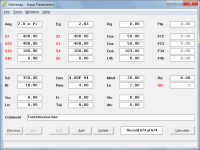
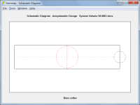
Should I rely on Winisd for a bass reflex or HR for TL? Is this a BR or TL?
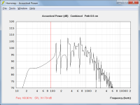
In Hornresp you can model it as either, the results will be the same.
Attachments 1 to 3 - Bass Reflex (lossless)
Attachments 4 to 6 - Transmission Line (with BR internal end correction added)
Attachments

Thanks David, thats awesomeIn Hornresp you can model it as either, the results will be the same.
Attachments 1 to 3 - Bass Reflex (lossless)
Attachments 4 to 6 - Transmission Line (with BR internal end correction added)
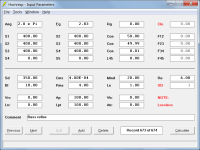
I am having another issue that has me stumped. Is the process for parallel wall pipe segments totally different from tapered segments?
3 segment pipe = 6 faces =
Needs data in S1 to S4 = 4 faces
This is the table, Ignore the 'mm', it's representing the area and each pipe is 500mm long
Drawing the pipes. I take it that the fat end is S1 and the skinny end is S4. What is stopping me in tracks with HR is to where to apply S2 and S3
Has this been an issue for anyone else? Is the middle pipe width S1 too, or S2 or S3? Are the two internal openings S1 or S2 or S3 or even S4 for the second one. I can't translate HR output to CAD without knowing where to apply these values from HR. I have asked about this previously without any feedback from anyone
Does anyone know how to apply these?
Model your cab. Subtract that cab volume from a block of air. Measure xsec areas along the line length of the air volume where appropriate. If quarters are shallow/tight, be sure to subtract the xsec area of the driver where appropriate. Plot that curve S(x) and it will be apparent what you need/want to capture in your sim models. Lather, rinse, and repeat until sick of drudgery iterating and revising both cad and sim models, then visit Brian's diysubwoofers.org and poke around in boxplan configs for an easier way 🙂 Alternatively, work only on the block of air. Review what David posted above vs the shape you get with your plotted areas.
Last edited:
Are you saying to loft the taper folded through a volume? But S1-S4 naturally fits a tapered fold so its not difficult to plot, my question is about applying S1-S4 to the three physical pipes with parallel sides. Difficult to review without being able to plot firstReview what David posted above vs the shape you get with your plotted areas.
Most-respectfully, just keep reading until you understand what David modeled for you. F1 is good, too.
Hmm, it's my understanding that historically HR only uses CSA of circular pipes, so convert CSA to whatever square/rectangular shape you want.
It is apparent that you guys are very highly educated in this and everything else that it takes to put this together. I made the wrong choices and didn't finish high school. I can follow some things from GM. He uses terms that I can look up and is kind enough to share resource links to help follow and understandMost-respectfully, just keep reading until you understand what David modeled for you. F1 is good, too.
I was glad to hear David say that it can be modelled as either, and very appreciative that he took the time to show by example. For the first one, he did 2 identical pipes and a stepped one. Not tapered! There is absolutely no way to keep 4 varying faces from a taper fair and map it to 3 varying cross-sections. Something needs to be assumed, and I thought I was lacking the education and sense to make the correct assumption. Turns out it is an input issue
To date, I couldn't insert a different value for SD at the step, as the last S* in one row wants to be the same as the first S* in the next row in Hornresp and my previous queries re this didn't attract any input. I noticed the red labels were different in David's pic and realised that I could change that to S*S and now am able to model in steps too. The whole time I kept talking taper when all along it was steps and that I had to convert the taper to steps to use the program correctly
I realise that I have been made sport off and take it in good spirits, but do wish you guys had pointed out to change that setting. All is well, armed with that, I can try to make cabs that work like the sims
Sorry man, I think you misunderstood my last query. I am ok with converting from circular to rectangular. I was having trouble creating the step due to having missed a setting in Hornresp and having learnt the program from a tutorial on tapering that missed this little detailHmm, it's my understanding that historically HR only uses CSA of circular pipes, so convert CSA to whatever square/rectangular shape you want.
- Home
- Loudspeakers
- Subwoofers
- Is it a bass reflex or TL?