You might get more responses asking this question in the Analogue Line Level subforum, even though many here in Multi-Way have done the same.
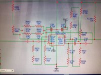
Hi,Schematic: (for some reason the site wasn't letting me publish schematic and message togheter). Ignore the 47K resistor at the output. Zoom the image to get rid of the artifacts.
Did you take a look on what I posted on Sunday at 8:43 PM"?
I designed the complete crossover (3 bands) and simulated it with separate frequencies and all summed exactly they way you are looking for, following the formulas found in the website www.linkwitzlab.com.
In addition, I think you are using very low resistors (1.2k) and big capacitors (1uF) for opamp filters.
Try bigger resistors (something between 10k and 100k) and smaller capacitors (smaller than 470nF, so you can use easy to find, smal size and cheap poliester film capacitors).
At line level, hundreds of milivolts, noise or interference is not much an issue.
Another suggestion: try to create the schematics the way I posted, for example, using the opamp symbols and each stage or functional blocks of you circuit well separated so as to make it easy to understand and debug. If you don't draw a circuit with the structure of it in mind, it is very difficult to "read" the schematic.
Input to output: from left to right.
Cascade filters: each block from left to right until reach the output.
Bipolar transistors, if any, try to use their orientation from top down: collector, base and emitter or mosfets: drain, base and source.
Use distributed GND's intead of running connections all over the circuit just to get to the unique GND.
Try to think the whole circuit as a group of interconnected blocks.
I'm just giving you some suggestions (and personal opinions) since you mentioned that you are 18 and you are still learning.
Other people might agree or disagree - there are many different ways of thinking due to many tradeoffs you have to make when designing circuits.
Last edited:

Of course i did, but i saw that one of the flattest simulatons was done by witwald by substituting the 20Hz HPF and 20000Hz LPF with butterworth filters instead of linkwitz-riley.
Perhaps i actually found a small piece of software made by Texas Instruments that can easily calculate the butterworth filters for me. I already designed the Linkwitz-Riley ones. (I used 1uF capacitors and similar for the low frequencies filters because i already have them). Now i only have to buy few SMD resistors and small value capacitors for the higher frequencies filters. The total cost is less than 30€ which is good.
Now i'm checking as much as i can if that software is actually producing the right schematic for a butterworth filter.
Expecially for the 20kHz one. I modified it to be a 21kHz 6th order one, so that all the frequencies all the way up to 16kHz are passed with exactly the same amplitude (perfectly flat). Then from 21kHz it rolls off VERY fast.
If everything is right, i will proceed with a final schematic that i can convert to a PCB that i can order online.
It will take a while to design a decent layout, i will follow the reccomendations that i found in the NE5532 Ti datasheet.
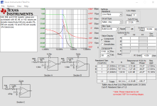
Only one OpAmp will be different, the one used for the 3th stage of the 6th order 21kHz butterworth filter. For some reason, the software tells me that the 3rd stage OpAmp must have a gain bandwith product of AT LEAST 15.1 MHz. Yes, MHz with an M. I dont know why, but i dont think it's wrong if this software is really by TI. Anyway, the NE5532 has a GBW of 10MHz which is not enough. So i picked a different one (also made by TI) that has a GBW of 40MHz at unity gain. I dont remember the exact part number, it was one of the OPA ones. Perhaps OPA1611.
After ALL of this... Time to design the actual box. I'll do my best. It's not going to be the absolute best of the best, but definetly enough for my ears.
Thank you all for the help
😉
Perhaps i actually found a small piece of software made by Texas Instruments that can easily calculate the butterworth filters for me. I already designed the Linkwitz-Riley ones. (I used 1uF capacitors and similar for the low frequencies filters because i already have them). Now i only have to buy few SMD resistors and small value capacitors for the higher frequencies filters. The total cost is less than 30€ which is good.
Now i'm checking as much as i can if that software is actually producing the right schematic for a butterworth filter.
Expecially for the 20kHz one. I modified it to be a 21kHz 6th order one, so that all the frequencies all the way up to 16kHz are passed with exactly the same amplitude (perfectly flat). Then from 21kHz it rolls off VERY fast.
If everything is right, i will proceed with a final schematic that i can convert to a PCB that i can order online.
It will take a while to design a decent layout, i will follow the reccomendations that i found in the NE5532 Ti datasheet.
Only one OpAmp will be different, the one used for the 3th stage of the 6th order 21kHz butterworth filter. For some reason, the software tells me that the 3rd stage OpAmp must have a gain bandwith product of AT LEAST 15.1 MHz. Yes, MHz with an M. I dont know why, but i dont think it's wrong if this software is really by TI. Anyway, the NE5532 has a GBW of 10MHz which is not enough. So i picked a different one (also made by TI) that has a GBW of 40MHz at unity gain. I dont remember the exact part number, it was one of the OPA ones. Perhaps OPA1611.
After ALL of this... Time to design the actual box. I'll do my best. It's not going to be the absolute best of the best, but definetly enough for my ears.
Thank you all for the help
😉
Hi,
Why do you need to roll off at 6th order filter slope above 20kHz?
If this system is intended to play music from recorded source, digital or analog, there is not much power above 20kHz to worry about.
Even if you intend to use microphones to capture live sound. You can safelly roll off at 12dB, if you think there will be ultrassonic signals. Popular mics used for P.A rarelly respond above 20kHz.
Rolling off below 20Hz with agressive slope has some reason, since it can protect the woofers from subsonic unintended noise or other spurious sound (connector failures, equipment power up etc). Even for this purpose, something between 2nd and 4th order is more than enough.
I don't see a point of using 6th order filters for audio crossovers.
Extremelly high Q in parametric equalizers is a different story, since the intention is to apply notch filters (stop band filter) to correct speaker and/or room imperfections, resonances, avoid mic feedback and this sometimes must be applied within a very narrow band. But general crossovers are not the case.
Several comercial equalizers, active crossovers, mixers were made using TL-07x which has a 5MHz gain bandwidth and works perfectly fine for this purpose of building filters limited to 2nd to 4th orders.
Could you indicate the TI software which mentions the need of GBW of 15.1MHz so I can take a look on it?
In the plot below, I've used frequencies that are 1/10 of those mentioned above. For example, 2.1kHz in the plot can be taken to correspond to 21kHz. I had to do this to work around the limitations in setting the axis limits in VituixCAD to get the plot to display the way I wanted it to....I modified it to be a 21kHz 6th order one, so that all the frequencies all the way up to 16kHz are passed with exactly the same amplitude (perfectly flat). Then from 21kHz it rolls off VERY fast.
The cyan dashed-dotted line in the plot below corresponds to a 2nd-order Butterworth low-pass filter response with −3dB point at 2.1kHz. It is seen that at 1.6kHz the response is −1.3dB. The other curve corresponds to a 6th-order Butterworth low-pass filter response with −3dB point at 2.1kHz. At 1.6kHz this filter is −0.2dB. The difference between the two filters is 1.1dB at 1.6kHz, which is very small.
I understand the preference for the more "perfectly flat" response afforded by the 6th-order filter. However, with that behavior, there comes a lot of attendant phase shift. As mentioned by @ron68, there is not a lot of energy in music above 20kHz, so the additional attenuation is really not necessary. Keep in mind that music on CDs will be very heavily attenuated above 20kHz, as a result of the steep anti-aliasing filters that are used.
If you still wish to use a high-frequency low-pass filter to give some degree of protection against high-amplitude high-frequency signal content, then consider using a 2nd-order Butterworth low-pass filter set to 30kHz.
In the plot below, I've modeled a 3kHz 2nd-order Butterworth low-pass filter, and it has a similarly low amount of attenuation below 1.6kHz as the 6th-order low-pass filter set to 2.1kHz.
Can you provide some further details of the drivers you plan to use, such as their frequency bandwidth limits, response plots, model numbers, etc?The speaker drivers I'm going to buy are high quality ones, with very flat frequency responses across the board.
I think that a little bit of clarification might be called for here. The simulations that were done were a quite simplified situation compared to that which will occur when real drivers are used that have their own frequency response functions....I saw that one of the flattest simulations was done by witwald by substituting the 20Hz HPF and 20000Hz LPF with Butterworth filters instead of Linkwitz-Riley.
To try and get some idea of what effects might be important, I have created a VituixCAD simulation of a three-way system that utilizes active crossover filtering. The schematic diagram and the plot of the results is shown below.
The natural response of the woofer is modeled using a 30Hz 4th-order Butterworth HPF (high-pass filter) and a 1500Hz 2nd-order LPF (low-pass filter). The HPF is 4th-order one on the assumption that the woofer is mounted in a vented box and tuned to a maximally-flat alignment without any low-frequency response ripple. The LPF is a guesstimate of the behaviour of a large woofer driver at high frequencies.
By using these HPF and LPF sections to simulate the inherent natural response of a driver, the model of course incorporates the phase response of the natural bandpass response of the driver. This needs to be taken into account in any crossover network design, and it can have a large bearing on the overall summation of the individual filtered responses of each of the drivers.
The natural response of the midrange is modeled using a 100Hz 2nd-order Butterworth HPF and a 4000Hz 2nd-order LPF. Finally, the natural response of the tweeter is modeled using a 1000Hz 2nd-order Butterworth HPF and a 20000Hz 2nd-order LPF.
There is a bandpass filter applied to the woofer. It consists of a 2nd-order Butterworth HPF set to 30Hz and a 4th-order Linkwitz–Riley LPF set to 150Hz. The HPF will help to greatly reduce cone excursion in the woofer when subjected to infrasonic low-frequency energy. A lower frequency, say 20Hz, would likely prove to be similarly effective, while helping to maintain low-frequency output down to 30Hz.
Next, there is a bandpass filter applied to the midrange. It consists of a 4th-order Linkwitz–Riley HPF set to 125Hz and a 4th-order Linkwitz–Riley LPF set to 4000Hz.
Finally, there is a 4th-order Linkwitz–Riley HPF set to 4000Hz applied to the tweeter.
I've also included active gain components on each of the driver signals. The ones on the woofer and tweeter have been used to add some positive gain to achieve as flat a summed response as possible. The adjustments needed were +0.7dB on the woofer, and +0.5dB on the tweeter.
The entire model has been configured as if all three drivers are coincident. This is evident when looking at the (X,Y,Z) coordinates of each driver, which are all 0m. In reality, it would be prudent to choose a design axis, say on the tweeter axis, and then at the very least to specify the relative Y offsets to simulate the effects of inter-driver time delays to the listening position.
Last edited:
Sorry for the delay, i was busy in theese last days.
For the crossover for now i'm aiming only on electrical flatness. All the other adjustments will be done later. I'm not going to make everything this perfect, since it's outside my field of expertice.
For now i just wanted the crossover to have good electrical flatness.
Regarding all the phase cancellaton stuff, i'll take care of all of that when i properly learn how to do it.
Regarding all the driver's frequency responses and other parameters, i'm still figuring out how to understand them correctly to choose the best drivers as possible. They will also have a very, very flat frequency response. For now i can't give a definite answer.
For now i just wanted to make a part of the project. The active crossover.
Here is the screenshot of that program that told me to use an OpAmp with 15.1 MHz GBP:
Edit: i have to take that screenshot again, for no apparent reason some screenshots just delete themselves from my phone. I have no idea of how is that possible...
You're right. With EQ you can fix any driver response. Therefore the difference is their off-axis behaviour..Regarding all the driver's frequency responses and other parameters, i'm still figuring out how to understand them correctly to choose the best drivers as possible. They will also have a very, very flat frequency response. For now i can't give a definite answer.
In the end, i definetively set to build this filter:
Subwoofer bandpass:
25 - 125Hz (4nd order Butterworth + 4nd order Linkwitz-Riley)
Midrange bandpass:
125 - 4000Hz (4nd order Linkwitz-Riley + 4nd order Linkwitz-Riley)
Tweeter bandpass:
4000 - 21000Hz (4nd order Linkwitz-Riley + 6th order Butterworth).
- All capacitors used in the filters are polypropylene ones.
-All resistors used in the filters are SMD film resistors with very low thermal noise of ±25ppm / °C and ±10ppm °C (0805 package).
-Dual isolated and linearly regulated power supply for the OpAmps to keep noise essentially at 0.
All components are on their way!
Now i just need to make the PCB file. The last step.
Does it look good?
Edit: in regard to why i'm choosing 6th order butterworth LPF for the tweeter, it is indeed to block high frequencies harmonic or inteferences. I noticed that adding this filter actually reduces noise in my class D amplifiers.
Subwoofer bandpass:
25 - 125Hz (4nd order Butterworth + 4nd order Linkwitz-Riley)
Midrange bandpass:
125 - 4000Hz (4nd order Linkwitz-Riley + 4nd order Linkwitz-Riley)
Tweeter bandpass:
4000 - 21000Hz (4nd order Linkwitz-Riley + 6th order Butterworth).
- Variable gain stage added to each bandpass filter
- Volume knob added to each bandpass filter
- All OpAmps are now OPA1612
- All capacitors used in the filters are polypropylene ones.
-All resistors used in the filters are SMD film resistors with very low thermal noise of ±25ppm / °C and ±10ppm °C (0805 package).
-Dual isolated and linearly regulated power supply for the OpAmps to keep noise essentially at 0.
All components are on their way!
Now i just need to make the PCB file. The last step.
Does it look good?
Edit: in regard to why i'm choosing 6th order butterworth LPF for the tweeter, it is indeed to block high frequencies harmonic or inteferences. I noticed that adding this filter actually reduces noise in my class D amplifiers.
Last edited:
Here is the screenshot of the TI software (Sorry again for the delay).Could you indicate the TI software which mentions the need of GBW of 15.1MHz so I can take a look on it?
Attachments
Not an expert but I think you can calculate your filter by using the VCad OPA library and by tuning the various blocks.In the end, i definetively set to build this filter:
Subwoofer bandpass:
25 - 125Hz (4nd order Butterworth + 4nd order Linkwitz-Riley)
Midrange bandpass:
125 - 4000Hz (4nd order Linkwitz-Riley + 4nd order Linkwitz-Riley)
Tweeter bandpass:
4000 - 21000Hz (4nd order Linkwitz-Riley + 6th order Butterworth).
- Added high capacity polypropylene DC blocking capacitors at the output of each bandpass filter (in all cases it will form a high pass filter with 3Hz cutoff, which can be ignored)
- Variable gain stage added to each bandpass filter
- Volume knob added to each bandpass filter
- All OpAmps are now OPA1612
- All capacitors used in the filters are polypropylene ones.
-All resistors used in the filters are SMD film resistors with very low thermal noise of ±25ppm / °C and ±10ppm °C (0805 package).
-Dual isolated and linearly regulated power supply for the OpAmps to keep noise essentially at 0.
All components are on their way!
Now i just need to make the PCB file. The last step.
Does it look good?
Edit: in regard to why i'm choosing 6th order butterworth LPF for the tweeter, it is indeed to block high frequencies harmonic or inteferences. I noticed that adding this filter actually reduces noise in my class D amplifiers.
Last edited:
- Home
- Design & Build
- Electronic Design
- Is butterworth filter good for audio?