Alright! Thank you.
The only thing is that i can't find a General schematic about the Linkwitz-Riley filter. I need it to design my own. I don't know the formulas for calculating its capacitors and resistors as well...
I think i need help... Thanks.
The only thing is that i can't find a General schematic about the Linkwitz-Riley filter. I need it to design my own. I don't know the formulas for calculating its capacitors and resistors as well...
I think i need help... Thanks.
There is good information in their site.
https://www.linkwitzlab.com/filters.htm
Do you play with circuit emulation? Pspice?
Do you plan 12dB/oct or 24dB/oct?
I'll be travelling in the next days, but I can help after Christmas.
https://www.linkwitzlab.com/filters.htm
Do you play with circuit emulation? Pspice?
Do you plan 12dB/oct or 24dB/oct?
I'll be travelling in the next days, but I can help after Christmas.
I just needed the schematics and the formulas. Schematics for 4th order Linkwitz Riley filter. For the butterworth i already know schematic and formulas.
I am going to use that combination of butterworth and Linkwitz to achieve Best flatness. There is only 1dB variation max, hopefully it is not very noticeable.
I am going to use that combination of butterworth and Linkwitz to achieve Best flatness. There is only 1dB variation max, hopefully it is not very noticeable.
Here's the fly in the ointment which some have pointed out.But looking at one of the graphs posted here there are still peaks, somehow. How can i attenuante them?
If the combination of a Linkwitz Riley filter and the driver response turns out to look more like Butterworth, then it's Butterworth, not Linkwitz Riley. Also, what makes a Linkwitz Riley filter.. the shape of one or the relationship between woofer and tweeter?
Maybe you have to use different filters for each end.

I just needed the schematics and the formulas. Schematics for 4th order Linkwitz Riley filter. For the butterworth i already know schematic and formulas.
For an active filter, it's quite simple: just cascade two Butterworth filters of half the order. For example, if you want a fourth-order Linkwitz-Riley low-pass active filter, design a second-order Butterworth active low-pass filter, make two of them and connect the output of the first to the input of the second. The two Butterworth low-pass filters now together form a fourth-order Linkwitz-Riley low-pass filter. It's more complicated for passive filters.
Alright, thank you! Also i noticed the schematics and formulas are all in the link that ron68 provided to me.
Thank you all so much for all that information. I knew nothing about all of this. Of course... That seemed too simple! Electronics are definetly not simple. They are in fact the most complex thing we have.
Now i can finally design this filter, even though it's not going to be absolute perfection with all that compensations and stuff missing, it is still enough for me. It will sound decently.
The Bluetooth module is also a LDAC one from Qualcomm for best audio quality and 0 'bluetooth noise'. It is going to be powered with one B1212S-3W DC voltage isolator and L7809 to keep noise at 0.
All capacitors used in the filters are polypropilene. All electrolythic capacitors in the power Electronics, amplifier and power supply for the filters are as good as they can get, very high ripple current capabilities and rated 10000+ hours of lifespan @ 105 °C.
The power supply for the filter's OpAmps is a dual isolated one, made with two B2424S-3W voltage isolators and L7815 and 7915 to obtain noise-free isolated ±15V. Small ceramic bypass capacitors are added very close to every NE5532 dual op-amp chip.
The layout in all the circuit boards will be ad good as possible. The amplifiers are already built, they have a perfectly flat frequency response and basically 0 noise floor. Can do 260W rms per channel with 1% THD+N. (Not the best i know, but good enough for me).
This is because the amplifiers are class D. High efficency is priority here, since this will be a big transportable speaker with a battery inside. It is a lithium Iron phosfate one with a capacity of 1kWh.
The speaker drivers i'm going to buy are high quality ones, with very flat frequency responses across the board.
Its going to be a fun project.
By the way... I'm just 18. Definetly not an expert, i have a loooooong way ahead of me at university...
Merry Christmas to everyone!
Hi,
I just tried the low pass using fo=125Hz and 24dB/oct.
See the results. After dinner (my napoletana pizza!), I'll try the other filters.
I followed the formulas below (from the site I indicated).
I defined the Fo, Q0 and C2.
R and C1 were calculated


I just tried the low pass using fo=125Hz and 24dB/oct.
See the results. After dinner (my napoletana pizza!), I'll try the other filters.
I followed the formulas below (from the site I indicated).
I defined the Fo, Q0 and C2.
R and C1 were calculated
The speaker i wanted to design is actually meant to be played outside, not inside.
It has one 400w RMS subwoofer, two 300w RMS midranges and two '200w RMS' tweeters.
I already tested one midrange at full volume and it is really loud, with no distortion.
By the way... I'm just 18.
Try not to get permanent hearing damage. I know from experience that loud music can very easily give you tinnitus, and once you have it, you have it for the rest of your life.
Definetly not an expert, i have a loooooong way ahead of me at university...
Merry Christmas to everyone!
Success at university, and merry Christmas to you and everyone else too!
Hi,
See the Linkwitz-Riley L4 (4th order) crossover actual simulation in OrCAD Capture.
It was easier than I thought 🙂
R and C were just chosen arbitrarily for simulation. Maybe I'd increase a bit the resistors to drain less current from opamps.
You can exercise the formulas in order to optimize the C and R for comercial values and/or associations.
The band-pass are just a cascaded block of low pass + block of high pass.
And remember, this is just the exact flat crossover electrical signal.
Acoustic flatness will only be achieved by measuring the speakers with a mic and adjust the circuit for it.
Since it will be active filter, at least you don't need to deal with speaker impedance afecting the crossover and you'll get a good start for your system.
You'll have to adjust the amp gains to compensate the speakers different sensitities.
Doesn't that forget that at the crossover point you have two drivers re-inforcing each other (in-phase), so that you need -6dB from each driver to sum to the same acoustic amplitude (on-axis)... Summing powers assumes the two drivers are uncorrelated, which is not the case...We could describe that verbally. Butterworth has flat power and flat response on the target axis. Linkwitz-Riley has a relative power dip by comparison.
For my project i will use that combination of linkwitz riley and butterworth filters to give that almost flat response.
The one that witwald proposed, which has the best flatness.
It has a 30Hz butterworth HPF connected to a LPF 125Hz Linkwitz-Riley one;
then a 125Hz HPF Linkwitz-Riley connected to a 4000Hz LPF Linkwitz-Riley one;
then a 4000Hz HPF Linkwitz-Riley connected to a 20000HZ LPF Butterworth one.
All of those filters are 4th order.
It is slightly flatter than the solution with all Linkwitz-Riley filters. So i'm going with this one.
I will choose the capacitors to be known commercial values, then the values of the resistors can be as crazy as they want, since i can easily get very close to them with precision 0.1% SMD resistors connected in series. I will keep the resistors below 6Kohm to keep the noise low, as i read in a TI article about that. The current will still be very low since the signal going into the filters is just 1V RMS. The NE5532 has no problem with this.
By the way, just to be on the safe side and not waste any components, is this the correct way to design a butterworth filter?
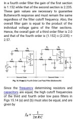
What i exactly mean is: Is the schematic, formula, and the fact that i need to make the gain of the first stage 1.152 and the gain of the second stage 2.235 correct to design a 4th order butterworth filter?
In the end i will post a final schematic here so that you can tell me if it is good or i made some mistakes.
It will contain more than just the filters connected togheter.
Attachments
The Butterworth signals are in quadrature.
Provided the crossover filter's order is odd.
You did not specify what your source is and what you amplifiers are. Most amplifiers have 30 dB of gain. Or 36 in case it is a bridged amplifier. My experience is the 100-200 mV output of a PC is too low for full power excitation of the power amplifier. 30 dB on 100 mV only gives 3.1V RMS
So a little additional gain from your filters might be beneficial. And a reason to choose "Equal component Sallen-Key configuration"
Two Butterworth 2nd order gives you a 4th order Linkwitz-Riley which is considered optimal for audio. In case you want a 4th order pure Butterworth (Q=0.7 and 3dB attenuation at Fc) you have to adjust the Q for each 2nd order Butterworth.
The Active Filter Cookbook by Don Lancaster giives accurate directions. Despite of the funny name it is better than you'd expect. Low pass filters on page 118.
Attachments
I have already some gain added after the filters. I calculated it such that when the volume of the preamplifier is at maximum, the output of the amplifier that i'm using will be almost at maximum.
The problem is that i actually dont know if i'm using the right schematic and formulas to design a 4th order Butterworth filter.
I posted an image that i found on a site, but i dont know if it is correct.
On that PDF i can't find how to design a 4th order butterworth filter...
The problem is that i actually dont know if i'm using the right schematic and formulas to design a 4th order Butterworth filter.
I posted an image that i found on a site, but i dont know if it is correct.
On that PDF i can't find how to design a 4th order butterworth filter...
It is good to start a user Account with Texas Instruments
Since their filter design calculators are rather top notch.
And depending on circuit topology if gain is needed or not.
Will be helpful selecting the proper op amp for stability.
Also there is ideal resistor values for low noise.
Or for actual board space. Ideal capacitor values so the capacitors are not excessively large.
Of course numerous tradeoffs involved and would be rather hair splitting to constantly redo the math.
Rather your goals are Ideal capacitor size or ideal resistor value.
And often tradeoffs with both. Modern " spread sheets" or filter designers will recalculate the filter.
Rather you make the capacitors or resistors as a constant. Likewise pointless to calculate a filter
with non standard capacitor or resistor values.
Those " perfectly flat " speaker responses will completely change anyway .
Once placed on a baffle. So as mentioned many times.
Filter Topology is not meaningless all together. But can be going by " Theory"
Real world depending on your baffle size and driver position. We are only interested in the actual phase.
So topologies will often be mixed regardless.
Again depending on the baffle size and how you mount your speakers.
The baffle is providing Half space loading, past the baffle is full space.
So those " flat" datasheet responses will be out the door.
Suggest a huge learning curve with Virtuix Cad
Model your exact baffle size and exact center to center spacing.
So you have a far far better idea of the drivers actual Phase/ Frequency Response.
Then they have Op Amp design calculators in VirtuixCad you can design the exact values needed for a filter.
Again modern spreadsheets will hold a set Capacitor value or resistor value constant to calculate a proper
Butterworth / Linkwitz etc etc using actual standard values and rather helpful
If your mid is 85 dB and your tweeter is 91 dB then what? your either padding passive.
Or whatever active filter you design. The gain if used active for mid will be different for each filter.
Point again, model the actual speakers, and model actual real filters being used not theory.
Last edited:
Yes, a big plus... I'd start the process with the generic active EQ blocks, just to gain an understanding of what needs to be done.Then they have Op Amp design calculators in VirtuixCad
I understood all theese problems, i can solve them after i design the filter.
I'm designing a filter with flat ELECTRICAL response to have a nice reference to make all the adjustments from for later.
Fow now i'm focused on designing the filter, but i have one main problem:
I cannot understand if what i'm making is an actual 4th order Butterworth filter, because i can't find any solid proof online about that.
Let's keep this simple:
I made this filter on a prototype board:
It has two sallen-key topology 2nd order filters connected togheter.
Filter resistors are equal values and filter capacitors are equal values.
In this case for 125Hz, using The formula Ft = 1 / 2*Pi*R*C and its inverse formulas, i calculated R = 1275 ohm (1.2K + 75R) and C = 1uF.
I used polypropilene capacitors and low thermal noise resistors (25 ppM °C).
The gain of the first stage is set to exactly 1.152220, and the gain of the second stage is set to exactly 2.234, for a total gain of 2.574.
Now my real question is: did i make a 4th order BUTTERWORTH filter?
Here is Also a schematic, but it's not very well made, i'm learning to make them much better. Use it as a reference if something i said before wasn't enough.
As i said before i'm asking for help here because i just couldn't find a solid proof that what i made is a proper 4th order butterworth filter.
Thanks in advance.
Last edited:
- Home
- Design & Build
- Electronic Design
- Is butterworth filter good for audio?