You don't.. but what is that choice. Are you trying to say there is only one right choice? if so, why?
exactly
they will sum with whatever Q is needed.
Without more data it is just wild guessing
or a rehash of the same old theoretical response.
Assuming its same old vertical alignment.
If he stays tight as possible with center to center.
4th order is good way to start
to achieve anything respectable in the vertical response.
You don't.. but what is that choice. Are you trying to say there is only one right choice? if so, why?
There are at least two choices that make sense, Linkwitz-Riley and odd-order Butterworth; each has its advantages and disadvantages. For the subwoofer, any order Butterworth could make sense if it is placed at the other side of the room, so you get large phase differences with the satellite speakers.
What really doesn't make sense to me is using even-order Butterworth for loudspeakers that are at about the same distance from the listener, and then equalizing out the resulting on-axis response bump. At least with a minimum-phase equalizer, that is an unnecessarily complicated way to make a Linkwitz-Riley filter: you cover the Butterworth poles with equalizer zeros and put the equalizer poles at the Linkwitz-Riley positions.
Last edited:

Yes, fair enough.
However I'm talking about the acoustic situation. The sound that reaches your listening position early, and the sound that goes into the room and reaches you late.
However I'm talking about the acoustic situation. The sound that reaches your listening position early, and the sound that goes into the room and reaches you late.
Even-order Butterworth gives a 3 dB peak on axis, while Linkwitz-Riley does not. If you want a flat response on axis and a flat response for the power averaged over all directions, you need odd-order Butterworth - but then the outputs of the crossover are not in phase (nor antiphase), causing a tilt of the main lobe and more sensitivity to small phase errors of the drivers than with Linkwitz-Riley.
@Gianluca_2000 , is the subwoofer to be placed such that it is at about the same distance from your ears as the mid and high, or do you put it wherever there is space in the room?
What would you say is small phase errors from the drivers ?
It can be quite big unlinearity between a midrange and a tweeter because of tweeters resonance point.
What about between sub and bass phase depending on both resonance point and selection of type of enclosure.
All this needs to be compensated for in the active filter in order to have a flat final result in the room.
Not easy, and as I see it impossible with a standard calculated filter that don't address phase from the drivers them self.
@MarcelvdG
Yes there are ways to handle it, but you need to know what you are doing and you need to have proper loudspeaker measurement system to verify the result.
Just selection topology between filters will not give a good final result.
The problem to solve is simply not that easy...
Yes there are ways to handle it, but you need to know what you are doing and you need to have proper loudspeaker measurement system to verify the result.
Just selection topology between filters will not give a good final result.
The problem to solve is simply not that easy...
@Gianluca_2000 Based on your description, I believe that you are expecting the summed response of the three filtered responses to sum to a flat response.
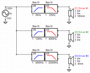
A high-level VituixCAD model of the situation is shown below. It consists of the 4th-order HP and LP Butterworth filters used to create three sets of bandpass responses. For the purpose of the examples, that follow, the frequency response functions of the drivers are assumed to be ideal, perfectly flat response functions for all frequencies.

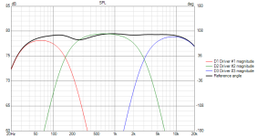
The above model produces the following bandpass response functions and overall summed response. Note that the summed response is not flat, peaking by about +2.5dB near each of the two crossover frequencies. This probably isn't the response that is desired.

Inverting the polarity of the Driver D2, we obtain the following, which is also far from ideal. Now we get severe dips in the response.

Let's change Butterworth filters to Linkwitz–Riley filters, keeping the order the same (i.e., 4th order).

As shown below, the summed frequency response is now much flatter.

Let's try changing the HP filter on Driver D1 and the LP filter on Driver D3 back to a Butterworth filter.

Now we obtain an improved, slightly flatter summed frequency response.

Of course, it must be kept in mind that all of the above simulations are reliant on the assumption that Drivers D1, D2, and D3 are ideal. That won't be the case in practice. Once each driver's frequency response function enters into the mix, then the results are unlikely to be as good as what has been shown above.
A high-level VituixCAD model of the situation is shown below. It consists of the 4th-order HP and LP Butterworth filters used to create three sets of bandpass responses. For the purpose of the examples, that follow, the frequency response functions of the drivers are assumed to be ideal, perfectly flat response functions for all frequencies.
The above model produces the following bandpass response functions and overall summed response. Note that the summed response is not flat, peaking by about +2.5dB near each of the two crossover frequencies. This probably isn't the response that is desired.
Inverting the polarity of the Driver D2, we obtain the following, which is also far from ideal. Now we get severe dips in the response.
Let's change Butterworth filters to Linkwitz–Riley filters, keeping the order the same (i.e., 4th order).
As shown below, the summed frequency response is now much flatter.
Let's try changing the HP filter on Driver D1 and the LP filter on Driver D3 back to a Butterworth filter.
Now we obtain an improved, slightly flatter summed frequency response.
Of course, it must be kept in mind that all of the above simulations are reliant on the assumption that Drivers D1, D2, and D3 are ideal. That won't be the case in practice. Once each driver's frequency response function enters into the mix, then the results are unlikely to be as good as what has been shown above.
Last edited:
Here is a VituixCAD model of the 3rd-order Butterworth filter approach.Even-order Butterworth gives a 3 dB peak on axis, while Linkwitz-Riley does not. If you want a flat response on axis and a flat response for the power averaged over all directions, you need odd-order Butterworth - but then the outputs of the crossover are not in phase (nor antiphase), causing a tilt of the main lobe and more sensitivity to small phase errors of the drivers than with Linkwitz-Riley.
This produces the following bandpass frequency response functions and summed frequency response. It's still very far from flat, with dips of about 3dB and lots of phase cancellation between the filtered responses.
Inverting the polarity of Driver D2 produces the following result. Here we have peaks instead of dips. The largest peak is about 1.9dB high.
These relatively poor results are produced because complementary 3rd-order Butterworth filters are very sensitive to phase errors through the crossover region. If we shift the locations of Drivers D1 and D3, we can achieve a better result.
Last edited:
You can also use a cascaded structure and an all-pass: two cascaded two-way crossovers and an all-pass in the path that only goes through one of the two.

The response from point A to the sum or difference between M and H has an all-pass characteristic, either second-order Q = 1 or first order, depending on the chosen speaker polarities (see https://www.diyaudio.com/community/...s-vs-group-delay-with-lr4.416178/post-7760275 ). Also apply such an all-pass to the L channel and the on-axis response should be flat again - with ideal drivers with a bandwidth from 0 to infinity and with perfecly aligned acoustic centres anyway.
The response from point A to the sum or difference between M and H has an all-pass characteristic, either second-order Q = 1 or first order, depending on the chosen speaker polarities (see https://www.diyaudio.com/community/...s-vs-group-delay-with-lr4.416178/post-7760275 ). Also apply such an all-pass to the L channel and the on-axis response should be flat again - with ideal drivers with a bandwidth from 0 to infinity and with perfecly aligned acoustic centres anyway.
If in doubt, rely on Butterworth.
If active, Bessel will suit.
If digital, inverse Chebychev is master.
If active, Bessel will suit.
If digital, inverse Chebychev is master.
I was curious about the possibility of using Bessel filters, as they don't have complementary combinations of lowpass and highpass filters.
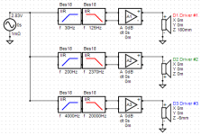
Below is a VituixCAD model of a 3rd-order filter configuration using the Bessel topology.

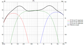
The bandpassed and summed frequency responses are shown below. It's not a particularly good result, with the largest of the two peaks being around 3dB high.

To improve the summed response, we can adjust the cut-off frequencies of the high-pass and low-pass filter sections of the filter block acting on Driver D2.

The above diagram shows that the frequencies of the filters acting on Driver D2 have been changed to 190Hz and 2240Hz. The summed response shown below is now much flatter, especially for that part of the spectrum involving the high-frequency Driver D3.

Below is a VituixCAD model of a 3rd-order filter configuration using the Bessel topology.
The bandpassed and summed frequency responses are shown below. It's not a particularly good result, with the largest of the two peaks being around 3dB high.
To improve the summed response, we can adjust the cut-off frequencies of the high-pass and low-pass filter sections of the filter block acting on Driver D2.
The above diagram shows that the frequencies of the filters acting on Driver D2 have been changed to 190Hz and 2240Hz. The summed response shown below is now much flatter, especially for that part of the spectrum involving the high-frequency Driver D3.
Attachments


I don't that last assertion - why would digital filtering involve Chebychev if analog doesn't? Chebychev filters have high phase distortion and are usually avoided if possible.If in doubt, rely on Butterworth.
If active, Bessel will suit.
If digital, inverse Chebychev is master.
That could be a mistake right there.I was looking for a filter as sharp as possible.
Sharp filters tend to ring in the time domain. There does not have to be any peak, as such, in the frequency response, although there is one, if you think of the overall spectrum as tilted instead of flat.
Look at the impulse response, and if you can see it swinging like a pendulum on a linear graph, then your ears will likely hear a lot more ringing with their logarithmic sensitivity.
Theoretically, you could get the speaker responses to stack up nicely, so overshoot and ringing cancels out. But with physical offsets and different directivity, it's pretty unlikely. The steepest classical filter type that avoids ringing altogether is the Bessel, but it wasn't designed to have symmetrical high-pass and low-pass complements. The Linkwitz-Riley is slightly softer but does sum together nicely.
Problem is real world drivers have rising or falling responses.
Then baffle step.
So it can be a combination of typical Bessel and Butterworth.
filters. typically have overlapping cut off points.
So theoretical behavior is more generic and confusing.
Since it has been expressed many times already.
There is no better or preferred answer.
Good to understand what can cause peaks or dips.
So when you observe the behavior with actual real drivers and real impedance curves.
How to remove it without wild guessing or why it is happening
and not waste your time.
Welp. For some reason even though i whatched this thread, i got no more updates from it via e-mail and missed Everything.
Firtly, i have to thank you so much for all this precious information and for your time, i will try to understand it is much as i can.
A lot of time has passed, but maybe you are still watching this:
There were things i didn't say.
The speaker i wanted to design is actually meant to be played outside, not inside.
It has one 400w RMS subwoofer, two 300w RMS midranges and two '200w RMS' tweeters.
I already tested one midrange at full volume and it is really loud, with no distortion.
Now i wanted flat response from my filters but now i discovered a major issue:
The cutoff frequency (1 / 2*3.1415*R*C) is calculated at -3dB! Meaning that the response would not be flat around the frequency cutoffs. This gets even even worse because the signal from the active filters gets amplified by a factor of 40, and the situation gets even even worse at the speakers. The 125Hz and 4000Hz frequencies (and the frequencies close to those two) are going to be attenuated really a lot, almost missing in the audio spectrum.
Thats why i wanted a filter that gives a very very flat response with not more than -0.5dB attenuation in the cutoff frequencies.
I dont know the schematics of the other kind of filters for now.
Hear this: it may be a terrible idea, but by doing a lot of testing i discovered that it is possible to make a butterworth filter that has very flat response.
Simply double the values of the capacitors in the filter, and make it VERY HIGH ORDER (Like 30+th order) so that a certain point from around 120Hz and below the attenuation rises REALLY FAST. This could be done for the other two cutoff frequencies as well (The 30Hz and 4000Hz ones). It is kind of expensive and requires a lot of componts, but it's not a problem for me.
I made two 125Hz 4th order filters with components so precise, that at 125Hz the ratio between the amplitude of the input and output signal is in fact 0.7085. Really really close to 0.707 (-3dB).
Since they are basically identical, I decided to use those two for this experiment.
I made them centered at 125Hz with the calculation Ft = (1 / 2*3.1415*R*C). After calculating the right capacitors, i simply doubled them (I used resistors such that i needed exactly 1uF capacitors. So doubled 2uF). After soldering the other capacitors to my two filters i connected them togheter in cascade to form an 8th order filter, and i meadured the voltage at the first stage, then at the second stage, first with a frequency of 125Hz. The voltage (amplitude) on the first and on the second stage is exactly the same at 125Hz.
Good, so i lowered the frequency to 120Hz and a small difference started to appear. At the first stage the amplitude decreased, but very slightly. Only around 10mV. But at the second stage, it decreased by another 33mV. So with just 5Hz below 125, the total amplitude decreased by 43mV in respect to the input signal. Thats what i want, but MUCH MUCH steeper. It does not have to be like ideal that at 120Hz i already see almost NO VOLTAGE, of course that would be impossibile. But i want it to be as steep as possible.
So i decided to make a third 4th order filter still very very precise like the other two (that took quite a while) and i connected it in cascade with the other two to make a 12th order one! Now, at 120Hz the attenuation of the signal in respect to the input signal raised to around 80mV.
At 125Hz though, the amplitude is still exactly the same as the input signal! Which means the filter is getting sharper without influencing 125Hz and above.
If i add more stages, the filter will eventually become as sharp as i wanted.
I know that maybe there is a much better solution that i'm not aware of, but for now i'm doing like this.
I'm doing this also because bass frequencies below 105Hz at high power (close to the power rating of the midrange) will cause it to bottom out. At 115 - 125Hz it works perfectly without distortion and without bottoming out.
So i will make that filter sharp such that the frequencies below 105Hz are attenuanted enough to not cause damage to the midranges.
Yes, i know, this will cause peaks at the cutoff frequencies now. But they will be accettable for me, since they will cover just a very narrow spectrum of frequencies.
I'm not aiming at absolute perfection. For me it is enough like this.
Tell me about what you think of this... Is there a better solution to exactly achieve what i described?
Also, there will be volume potentiometers for each 'speaker type'. The 30 - 125Hz range will have its volume knob, the 125 - 4000Hz its own volume knob, and the 4000 - 20000Hz its own volume knob. So that i can balance them like i want (the best combination i hear the best).
But i wanted the base frequency response to be as flat as possible, for as high fidelity as possible. The base frequency response is flat, then you decide how to modify it. So that you have a good flat reference to make your adjustments from.
Something that i forgot: the voltage measurements i made in the filter are RMS values. I don't have an oscilloscope...
At a -3dB cut-off point, the 2 intersecting drivers are simply running at half power, each. So, factoring in a slight phase shift, the total signal sums back to one (0dB). So that particular problem seems moot.Now i wanted flat response from my filters but now i discovered a major issue:
The cutoff frequency (1 / 2*3.1415*R*C) is calculated at -3dB! Meaning that the response would not be flat around the frequency cutoffs. This gets even even worse because the signal from the active filters gets amplified by a factor of 40, and the situation gets even even worse at the speakers. The 125Hz and 4000Hz frequencies (and the frequencies close to those two) are going to be attenuated really a lot, almost missing in the audio spectrum.
Thats why i wanted a filter that gives a very very flat response with not more than -0.5dB attenuation in the cutoff frequencies.
The bigger issue is probably the off-axis interference. In some cases, the strongest constructive interference does not point forward, but is tilted at some angle.
Hi, I see a lot of focus on electrical flatness and we should be focussed on acustical flatness.Welp. For some reason even though i whatched this thread, i got no more updates from it via e-mail and missed Everything.
Firtly, i have to thank you so much for all this precious information and for your time, i will try to understand it is much as i can.
A lot of time has passed, but maybe you are still watching this:
There were things i didn't say.
The speaker i wanted to design is actually meant to be played outside, not inside.
It has one 400w RMS subwoofer, two 300w RMS midranges and two '200w RMS' tweeters.
I already tested one midrange at full volume and it is really loud, with no distortion.
Now i wanted flat response from my filters but now i discovered a major issue:
The cutoff frequency (1 / 2*3.1415*R*C) is calculated at -3dB! Meaning that the response would not be flat around the frequency cutoffs. This gets even even worse because the signal from the active filters gets amplified by a factor of 40, and the situation gets even even worse at the speakers. The 125Hz and 4000Hz frequencies (and the frequencies close to those two) are going to be attenuated really a lot, almost missing in the audio spectrum.
Thats why i wanted a filter that gives a very very flat response with not more than -0.5dB attenuation in the cutoff frequencies.
I dont know the schematics of the other kind of filters for now.
Hear this: it may be a terrible idea, but by doing a lot of testing i discovered that it is possible to make a butterworth filter that has very flat response.
Simply double the values of the capacitors in the filter, and make it VERY HIGH ORDER (Like 30+th order) so that a certain point from around 120Hz and below the attenuation rises REALLY FAST. This could be done for the other two cutoff frequencies as well (The 30Hz and 4000Hz ones). It is kind of expensive and requires a lot of componts, but it's not a problem for me.
I made two 125Hz 4th order filters with components so precise, that at 125Hz the ratio between the amplitude of the input and output signal is in fact 0.7085. Really really close to 0.707 (-3dB).
Since they are basically identical, I decided to use those two for this experiment.
I made them centered at 125Hz with the calculation Ft = (1 / 2*3.1415*R*C). After calculating the right capacitors, i simply doubled them (I used resistors such that i needed exactly 1uF capacitors. So doubled 2uF). After soldering the other capacitors to my two filters i connected them togheter in cascade to form an 8th order filter, and i meadured the voltage at the first stage, then at the second stage, first with a frequency of 125Hz. The voltage (amplitude) on the first and on the second stage is exactly the same at 125Hz.
Good, so i lowered the frequency to 120Hz and a small difference started to appear. At the first stage the amplitude decreased, but very slightly. Only around 10mV. But at the second stage, it decreased by another 33mV. So with just 5Hz below 125, the total amplitude decreased by 43mV in respect to the input signal. Thats what i want, but MUCH MUCH steeper. It does not have to be like ideal that at 120Hz i already see almost NO VOLTAGE, of course that would be impossibile. But i want it to be as steep as possible.
So i decided to make a third 4th order filter still very very precise like the other two (that took quite a while) and i connected it in cascade with the other two to make a 12th order one! Now, at 120Hz the attenuation of the signal in respect to the input signal raised to around 80mV.
At 125Hz though, the amplitude is still exactly the same as the input signal! Which means the filter is getting sharper without influencing 125Hz and above.
If i add more stages, the filter will eventually become as sharp as i wanted.
I know that maybe there is a much better solution that i'm not aware of, but for now i'm doing like this.
I'm doing this also because bass frequencies below 105Hz at high power (close to the power rating of the midrange) will cause it to bottom out. At 115 - 125Hz it works perfectly without distortion and without bottoming out.
So i will make that filter sharp such that the frequencies below 105Hz are attenuanted enough to not cause damage to the midranges.
Yes, i know, this will cause peaks at the cutoff frequencies now. But they will be accettable for me, since they will cover just a very narrow spectrum of frequencies.
I'm not aiming at absolute perfection. For me it is enough like this.
Tell me about what you think of this... Is there a better solution to exactly achieve what i described?
Also, there will be volume potentiometers for each 'speaker type'. The 30 - 125Hz range will have its volume knob, the 125 - 4000Hz its own volume knob, and the 4000 - 20000Hz its own volume knob. So that i can balance them like i want (the best combination i hear the best).
But i wanted the base frequency response to be as flat as possible, for as high fidelity as possible. The base frequency response is flat, then you decide how to modify it. So that you have a good flat reference to make your adjustments from.
Something that i forgot: the voltage measurements i made in the filter are RMS values. I don't have an oscilloscope...
You do need to crossover frequencies for woofer, mid and tweeter, for sure. But being worried with some Hz up or down, some dB's up or down on electrical response it's not worth. Acoustic response of each driver will have a lot more influence (roll offs, cone breakups, resonances etc).
Choose one aligment (at least 12dB/oct) and adjust it to get an approximation just to have a baseline and protect the drivers.
The best way to go, it's to measure the response (with a calibrated mic) of your loudspeaker with all the speaker installed so as to account for differences in distances. Perform timed measurements, take frequency response of each speaker and load to the crossover simulation tool.
This way you will have geometrical (distances), electrical and acoustic responses - all summed together.
Then you adjust your crossover (passive or active) on the tool to as flat as possible - here yes, go to the "0.000" as possible.
I've learned this procedure here in DIY AUDIO, which opened my mind and I'm having a very good result with the last speakers I built/readjusted.
In the past I used to adjust the electrical flatness to the "0.000dB" and the final result never got correct - many changes by "ear" needed to achieve just a regular result.
Well... I dont have that kind of tools... nor the expertise to perform such tests...
BUT i actually forgot about the fact that the sum of - 3dB in the overlapping drivers sums up again to be the same. I will pick a 600W subwoofer instead of a 400W one then, paired with the two 300W midranges. At 125Hz the sub will run at 300w and the two mids at 300w as well (125w each). So that it will be balanced.
But looking at one of the graphs posted here there are still peaks, somehow. How can i attenuante them?
If you want to make sure at least electrical signal will be flat, just use the Linkwitz-Riley aligment (12dB/oct or 24dB/oct).
Transition will happen at -6dB and acustically it will sum up to 0dB if speakers have the same sensibility.
In your case, differences on speaker sensibilities will be compensated by the 3 individual amplifier gains (knobs).
Look at the simulation Witwald did on 2024-08-13 8:12 am - it is flat.
Linkwitz-Riley aligment gives you flat electrical response.
- Home
- Design & Build
- Electronic Design
- Is butterworth filter good for audio?