i d like to ask if somebody knows a test circuit to check these ic's..a circuit for example to apply the voltage,input signal,and with the osciloscope check the low side-high side outputs...thanks....
The high side out will either work or not and is totally dependant upon the output stage it is connected to.
The best test rig is an amplifier with no load.
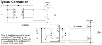
I would make up a test rig similar to infineon's data sheet.
The best test rig is an amplifier with no load.
I would make up a test rig similar to infineon's data sheet.
Attachments
Last edited:
let me see.....without the outputs fets i can see low side signal with scope.....ok?am i write?the high side i cannot see anything....am i missing something?
If Vs is not elevated, there will be no drive signal. The low side will pulse as normal.
Correct.
Correct.
I use a 9v battery on the high side to produce the high-side supply when there are no outputs.
Do you believe that there is a problem with the driver ICs or with some other IC on the driver board?
Did the outputs fail?
Do you believe that there is a problem with the driver ICs or with some other IC on the driver board?
Did the outputs fail?
generally,because, if the irs21844s fail all the fets blown in the most cases i want to be sure the way to check the drive signals.....i mean the low side looks ok but i wanna be sure both the high side with the oshilloscope....to be ok all the drive signals...sorry for the bad eiglish!!
i think i get it....not sure...if there is no output fets there is no high side signals?and if i put one fet per bank....?
There is no high-side drive because the high-side supply voltage is generated by the rail-rail oscillation that's only generated when the outputs are in the circuit.
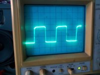

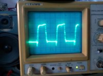
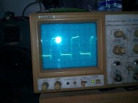
the 2 first pictures is the low side....3 and 4 high side....i have 20 degrees celcious at low side fets and 25 degrees celcious high side....is this normal? 50hz input signal to amplifier...
Without information about the scope settings, those are essentially useless.
Timebase?
Vertical amp setting?
Was the vertical amp set to 'cal'?
Was the probe set to 1x or 10x?
Was the trace set to the reference line prior to measuring?
AC coupling should almost never be used. Use DC coupling.
Do you know how to use your scope in differential mode?
Timebase?
Vertical amp setting?
Was the vertical amp set to 'cal'?
Was the probe set to 1x or 10x?
Was the trace set to the reference line prior to measuring?
AC coupling should almost never be used. Use DC coupling.
Do you know how to use your scope in differential mode?
timbase at 2μsec
vertical amp to cal position
probe to 10x
yes i was to reference line....sorry for the AC coupling....what you mean differential mode....sorry misundertood
low side 5v/din
high side 0,2v/din
vertical amp to cal position
probe to 10x
yes i was to reference line....sorry for the AC coupling....what you mean differential mode....sorry misundertood
low side 5v/din
high side 0,2v/din
please give me some specific information about this all process the waves of irs21844 and the scope....thank you very much for your time
Do you have the amp tutorial? If not, I'll copy and paste something here. I'm guessing that you were referring to using the scope in differential mode in post #13. If not, clarify.
good morning...no unfortunatelly i do not have it.....please im waiting your post....thanks again....
if you mean to use the scope in two channels the same time the scope has not that function.if i misunderstood sorry my mistake....
- Home
- General Interest
- Car Audio
- irs21844s help..