I’m not sure what purpose “C*” and “R*” serve or what tolerances are acceptable.
The resistor is easy as it calls for 1K which is no problem and I have it on hand.
The capacitor calls for a 1nF ceramic.
I only have some cheap Radioshack 10nF ceramic caps on hand…literally no other values in ceramic in my bins that I could find.
The only other option I could find in my bins in a 1nF value is some NOS RIFA poly caps I bought off eBay a while back.
Is either one OK or preferable?
I’m not sure what purpose “C*” and “R*” serve or what tolerances are acceptable.
just ignore those positions, do not populate them
I made error with those snubbers, at least judging by later knowledge, where it's called that each halve of secondary winding needs own snubber
anyhow, currents are so low that snubbing isn't really necessary

Hi ZM. I’ve got a few questions from your first post instructions as I prepare to power up and adjust my Pumpkin boards…my questions/comments are in bold I added some pics.
Your Instructions…
do not connect buffer output to Turtle
OK no problem…it’s not connected.
maximize trimpot R36 (measure across R39 to confirm max value)
I maxed out the 100ohm R36 trimpots before mounting them…but I want to confirm I did it correctly to be safe and soothe my OCD.
There is no R39 on my boards that I can find labeled.
Where can I measure to confirm R36 is set properly in my boards?
My PCB shots unpopulated:


R37 position is irrelevant for now
OK
if you're sure that you connected everything properly, just power it on
set positive and negative rails to +/-12Vdc , with trimpots R9 and R10
Do I measure this properly by placing probes at “U+” and “U-“ and the “GND” pads? See pic…

power off, place DVMdc crocs across R34, power On then fiddle with R36 to set 20mV across R34, then fiddle with R37 to set 0mV DC offset at output
These parts seem pretty clear. Since my “LOADING” resistor pads are unused and parallel to the output pads I can measure for DC offset there right?
do everything the same with other channel, connect outputs of buffers to Turtle, enjoy
Your Instructions…
do not connect buffer output to Turtle
OK no problem…it’s not connected.
maximize trimpot R36 (measure across R39 to confirm max value)
I maxed out the 100ohm R36 trimpots before mounting them…but I want to confirm I did it correctly to be safe and soothe my OCD.
There is no R39 on my boards that I can find labeled.
Where can I measure to confirm R36 is set properly in my boards?
My PCB shots unpopulated:
R37 position is irrelevant for now
OK
if you're sure that you connected everything properly, just power it on
set positive and negative rails to +/-12Vdc , with trimpots R9 and R10
Do I measure this properly by placing probes at “U+” and “U-“ and the “GND” pads? See pic…
power off, place DVMdc crocs across R34, power On then fiddle with R36 to set 20mV across R34, then fiddle with R37 to set 0mV DC offset at output
These parts seem pretty clear. Since my “LOADING” resistor pads are unused and parallel to the output pads I can measure for DC offset there right?
do everything the same with other channel, connect outputs of buffers to Turtle, enjoy
There is no R39 on my boards that I can find labeled.
Where can I measure to confirm R36 is set properly in my boards?
Measure across R33 and R35, the two 39 Ohm resistors in parallel with the pots.
YesDo I measure this properly by placing probes at “U+” and “U-“ and the “GND” pads? See pic…
Alright…no magic smoke…one channel adjusted 😎
Thnx IAIMH!
On to the second…
Thnx IAIMH!
On to the second…

Not a lot of time today…but second Pumpkin channel is up and running properly as well.
Only hiccup was some additional DC offset I had to dial out.
I thought my meter said about 49-50mV…next thing I knew it said 90mV again😳…yeah my old eyes missed the 1…it was 140-150mV.
Now on to the Logic and all those pesky little signal connections.
Only hiccup was some additional DC offset I had to dial out.
I thought my meter said about 49-50mV…next thing I knew it said 90mV again😳…yeah my old eyes missed the 1…it was 140-150mV.
Now on to the Logic and all those pesky little signal connections.
Good news and bad news…the story of life?
I was actually struggling with the logistics of how to mount my faceplate because I installed my “Tower of Power” right in the way of where I need to get its mounting bracket and hardware on the right hand side of the case😑
Other details of Logic wire routing and various house keeping aside…I decided I should try powering the thing up first to test.
Well, I got a warm welcome from ZM…

And even my own personal “high five” greeting…

Then the standard Logic display came up…

I started playing with the rotary control…volume level changed properly with the associated “clickity clack” of corresponding relays.
That’s where the fun ended.
When I tried pushing the rotary to change the source the display changed to the corresponding source numbers, but I got no “clickity clack” of corresponding source relays on either Pumpkin board.
There were several modifications made to the Pumpkin boards to accommodate for the Logic as instructed.
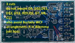
I posted the images of the PCB trace cuts previously…3 cuts on the top and 4 cuts in the bottom.
Here they are again along with the instructions of what components to not mount.


I’ve gone over the boards several times to confirm I stuck to the instructions of where to cut and what to not mount.
Beyond this…I decided to try the remote.
It didn’t have a battery installed and when I opened it there was no info as to the specific battery required.
I took a guess that it was a standard 3V car remote battery.
It didn’t work properly. The first attempt caused the screen to turn white and no further response from the Logic.
I tried power cycling the preamp…the fuses blew…LOL.
I’ve got it powering on again, but haven’t tried anything else.
Pics of Pumpkin boards in case right now…


Not sure where to begin. I did post pics of the trace cuts on the actual PCBs at one point as well.
I think you can see the various diodes (d7-d13), c11, q5 and r29 are not mounted. I can post the PCB trace cuts again…but they match the images with the instructions above.
The only other modification I did was to remove all the diodes on the Turtle board…that works fine as far as I can tell.
I was actually struggling with the logistics of how to mount my faceplate because I installed my “Tower of Power” right in the way of where I need to get its mounting bracket and hardware on the right hand side of the case😑
Other details of Logic wire routing and various house keeping aside…I decided I should try powering the thing up first to test.
Well, I got a warm welcome from ZM…
And even my own personal “high five” greeting…
Then the standard Logic display came up…
I started playing with the rotary control…volume level changed properly with the associated “clickity clack” of corresponding relays.
That’s where the fun ended.
When I tried pushing the rotary to change the source the display changed to the corresponding source numbers, but I got no “clickity clack” of corresponding source relays on either Pumpkin board.
There were several modifications made to the Pumpkin boards to accommodate for the Logic as instructed.
I posted the images of the PCB trace cuts previously…3 cuts on the top and 4 cuts in the bottom.
Here they are again along with the instructions of what components to not mount.
I’ve gone over the boards several times to confirm I stuck to the instructions of where to cut and what to not mount.
Beyond this…I decided to try the remote.
It didn’t have a battery installed and when I opened it there was no info as to the specific battery required.
I took a guess that it was a standard 3V car remote battery.
It didn’t work properly. The first attempt caused the screen to turn white and no further response from the Logic.
I tried power cycling the preamp…the fuses blew…LOL.
I’ve got it powering on again, but haven’t tried anything else.
Pics of Pumpkin boards in case right now…
Not sure where to begin. I did post pics of the trace cuts on the actual PCBs at one point as well.
I think you can see the various diodes (d7-d13), c11, q5 and r29 are not mounted. I can post the PCB trace cuts again…but they match the images with the instructions above.
The only other modification I did was to remove all the diodes on the Turtle board…that works fine as far as I can tell.
late night
need some more brain to check all pics I sent you.... vaguely remembering one bridge you need to install on IDC header on each channel pcb ....... but, tomorrow
remote battery is sorta standard 3V, type CR2032
need some more brain to check all pics I sent you.... vaguely remembering one bridge you need to install on IDC header on each channel pcb ....... but, tomorrow
remote battery is sorta standard 3V, type CR2032
no bridge needed, it was brain mist 
confirm that you have +24Vdc present on all Anode pads of (nonpopulated) diodes at relays; ref to GND of logic, practically the case itself
confirm that you have +24Vdc present on all Anode pads of (nonpopulated) diodes at relays; ref to GND of logic, practically the case itself
Yes it was late and I walked away.
I’m up now, but brain is mush from head cold and need to get kiddo to school.
The battery was CR2032…which I figured was pretty standard. Didn’t mount back plate of remote during test…maybe that screwed something up?
Will check for 24V at relay diode-anode pads a little later.
I’m up now, but brain is mush from head cold and need to get kiddo to school.
The battery was CR2032…which I figured was pretty standard. Didn’t mount back plate of remote during test…maybe that screwed something up?
Will check for 24V at relay diode-anode pads a little later.
Didn’t mount back plate of remote during test…maybe that screwed something up?
first thing I forgot to wrote: check logic rails at Logic pcb itself: +5V, +24V, both ref. to Logic GND;
basic functionality must be there with encoder ( volume and inputs)
remote is ...... well, next layer of functionality
when you confirm having +24Vdc on anode diode pads, ref to logic GND, you can check each relay separately
first confirm continuity between Logic GND and case; it's necessary per se ( to burry any possible interference) and handy for checking things
put croc clip to case, then wire from same to cathode diode pad near each relay, and it is same as enabling (circuit to ) logic GND with circuitry itself - you'll hear click if relay engages
if you leave flat cable connected to second/other channel pcb, same position relay will click on both channel pcbs
OK…did some quick tests.
I checked that I have all the proper voltages and ground continuity at the Logic PCB.
Everything there is good. The ground rings out to my chassis ground lug and the 24V and 5V pads are within .08V of their specified values.
When I moved on to measure the voltage at the anode pad for each source selecting relay I did not get the proper voltage. I am only measuring .623V there….for all them.
Afterwards, I went on to measure voltage on the Turtle PCB at the anode pad for various relays. All came up at about 24V. This makes sense since they are responding properly.
Any idea why I don’t have proper voltage for the source relays?
P.S. I put the CR2032 back in the remote and closed it up. Tried pushing various buttons. The “up” button caused it to power cycle twice (I think I pushed it twice by accident)…afterwards Logic was unresponsive.
Power cycled the preamp at the power entry module. Then I tried another button…heard a single click…no change to display…then it was unresponsive again.
Last edited:
remove smaller IDC connector from logic pcb
measure do you have +24Vdc at first 2 and last 2 pins at IDC conector marked "input switching"
I believe I made wire bridge at back of pcb to have +24Vdc connected there (so to accommodate for your case), so please check that
we will solve remote issue when we solve basic stuff
ps. be sure that you're checking +24Vdc at diode pads near relays at anode (not cathode, that's ring/strip)
OK
I confirmed I have 24V at first 2 and last 2 pins of IDC connector on Logic PCB…all is good there.
Yes, I can see the small bridge on the back of the Logic PCB between pins of the IDC header.
I tested for voltage at the anode pads for the source relays after referencing this diagram…

So my measurements are correct I think.
Currently scratching head and staring at Pumpkin PCB and wondering where to test next.
EDIT: I was able to test and confirm 24V is getting to Pumpkin PCBs through the ribbon cable.
I got 24V at the anode pad of D8 where a trace comes straight off first two pins if IDC header on Pumpkin PCB. Also got 24V on unpopulated pad of Q5.
Searching to test elsewhere.
I confirmed I have 24V at first 2 and last 2 pins of IDC connector on Logic PCB…all is good there.
Yes, I can see the small bridge on the back of the Logic PCB between pins of the IDC header.
I tested for voltage at the anode pads for the source relays after referencing this diagram…
So my measurements are correct I think.
Currently scratching head and staring at Pumpkin PCB and wondering where to test next.
EDIT: I was able to test and confirm 24V is getting to Pumpkin PCBs through the ribbon cable.
I got 24V at the anode pad of D8 where a trace comes straight off first two pins if IDC header on Pumpkin PCB. Also got 24V on unpopulated pad of Q5.
Searching to test elsewhere.
Last edited:
if you have +24Vdc at logic pcb header, outer pairs, then with flatcable connected - you must have present same voltage at same pins on channel pcbs, IDC headers
remove flat cable from channel pcbs, confirm that you have continuity between mentioned pins and anode pads of diodes
btw. all anode pads are on same trace, shorted/common for all relays
remove flat cable from channel pcbs, confirm that you have continuity between mentioned pins and anode pads of diodes
btw. all anode pads are on same trace, shorted/common for all relays
which points me to ........... one missing pic
there is no, as is, connection on channel pcbs between outer pins and anode pads
give me few mins, to check schm and will write what to do, without need to remove pcbs
there is no, as is, connection on channel pcbs between outer pins and anode pads
give me few mins, to check schm and will write what to do, without need to remove pcbs
here it is, observe red bridge drawn on pic
take tiny wire, make short between marked pads (anode of diode and source of mosfet)
take care that wire bridge is not having long mustaches, to avoid short to base plate
do the same on both channel pcbs
try functionality of source switching and volume only with encoder (rotation and push)
if remote is acting weird ( and it will, as I'm expecting) ....... I know what it is
even if I'm thoroughly testing each assembly after programming, recently I had few Gremlin-erratic cases - functional, functional , functional then crazy then aaaaargh! ....... and culprit was in recent Arduino libraries update;
after finding that issue, recalled old libraries from backup, and I forbid auromatic updates .... even nagging for updates
so, if remote is acting wild, you'll use it remote-less for few weeks, and you'll receive new Arduino board with bespoke flash
Attachments
Yes…I came to same conclusion.
D8 anode pad has 24V…but is dead end.
D7 anode would get 24V to first two relays…then I’d need more bridges to other relay anode pads I think.
Take your time…you’ll probably find a better solution!

EDIT: LOL…you’re too fast 👍
D8 anode pad has 24V…but is dead end.
D7 anode would get 24V to first two relays…then I’d need more bridges to other relay anode pads I think.
Take your time…you’ll probably find a better solution!
EDIT: LOL…you’re too fast 👍
just make that bridge, test, inform
anodes are all shorted/ on same trace
be it top or bottom copper, who cares
anodes are all shorted/ on same trace
be it top or bottom copper, who cares
- Home
- Amplifiers
- Pass Labs
- Iron Pumpkin(s) and other smaller vegetable animals, Tips 'n' Tricks thread