I assume this Antek 25VA dual 18V secondary will work fine?
https://www.antekinc.com/an-0218-25va-18v-transformer/
https://www.antekinc.com/an-0218-25va-18v-transformer/
it'll work no doubt, but if you got clicks in speakers while selecting inputs, blame switch, or Pa
Everyone who volunteered to be an early builder should have been contacted by the store. If you were not contacted, please PM me and let me know.
Thank you again!
Thank you again!

Hi All -
As mentioned, the Jim will be putting up a build thread in the near future. In the interim, we can keep the questions here and/or in the 'KISS' thread.
I've had a question or two re: the ribbon cables that go from the main boards to the 'twister boards'. They're not mandatory, but in his infinite wisdom, ZM made them to be directly compatible with industry standard 14-pin IDC. So, for a comparatively small amount of money, you have a mostly fool-proof way of wiring your input switching and LEDs. NOTE - As witnessed in the KISS thread, I originally did it without the ribbon cable for testing ... BAD IDEA (for me). I shorted the rails of the PSU mistakenly when testing my relays and a lot of parts went out with a flash and a poof. I strongly recommend using the cable.
I built my own, so I could cut them to a length I preferred for my chassis. Many people may not want to do that.
You can choose whatever length works for your personal build. Here are a few examples of parts from a popular online retailer. I did not look for the cheapest or the best source or the correct quantities. These are just examples. Mouser and Digikey sell them too, I think, if you're a one-stop-shop type of person. If you're a computer person, you may even have some laying around.
Female to Female Cables - 1 for SE 2 for balanced
https://www.amazon.com/uxcell-FC14P...trial&sprefix=14-pin+idc,industrial,95&sr=1-2
Male Box Headers (No, you don't need 28) You'll need 2 for SE and 4 for Balanced - https://www.amazon.com/gp/product/B01071U7EA/ref=ppx_yo_dt_b_search_asin_title?ie=UTF8&psc=1
Hope that helps!
Schematic posted in #61 shows R4 and R5 at 18ohm, while the BOM and Mouser cart I'm looking at say 15ohm for R4 and R5...which am I to believe?
I believe I read Vishay RN60D does not fit this board. Can anyone confirm or deny? I do not have boards in hand yet.
I believe I read Vishay RN60D does not fit this board. Can anyone confirm or deny? I do not have boards in hand yet.
Last edited:
^ I would not use RN60s. Too big physically, but you may be creative. Excellent call out re: R4 and R5.
@Zen Mod - We've had a few iterations. Should R4 and R5 be 15R or 18R or doesn't matter? In parallel with R3 and R6.
Specifically, we're referencing this latest schematic attached. Note... SE and Bal are the same for these positions. I can update as required.
@Zen Mod - We've had a few iterations. Should R4 and R5 be 15R or 18R or doesn't matter? In parallel with R3 and R6.
Specifically, we're referencing this latest schematic attached. Note... SE and Bal are the same for these positions. I can update as required.
Attachments

Did anyone happen to build a simulation in Spice? I mean the PS/regulator and buffer stages. I plan on building in stages: PS, then switching section, and lastly populating the buffer/autoforrer. Make sense? It would be nice to have a model to check voltages along the way….or at least a schematic with voltages noted.
This doesn’t look to be a simple build…it would be nice to have as many weapons in the arsenal as possible. Especially seeing this build will make its way into the store.
I suck at Spice…rather I haven’t had time to learn it. Maybe an esteemed colleague could build a model.
This doesn’t look to be a simple build…it would be nice to have as many weapons in the arsenal as possible. Especially seeing this build will make its way into the store.
I suck at Spice…rather I haven’t had time to learn it. Maybe an esteemed colleague could build a model.
Last edited:
Back home to do a few measurements. I'll do a quick BoM update noting pitch / size for resistors in addition to noting the 0207. Admittedly 0207 was new to me until ZM explained. 🙂
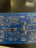
Pitch (space between the holes) is 10mm with the 'body' of the resistor in the silkscreen dimensioned to 7mm x 2mm. You can squeeze in something larger than 0207, and the leads for RN60s will fit the holes, but it would take some creativity to use them in all positions.
Here is a quick pic comparing an RN60, a generic 1/4 W resistor, and a CMF55 next to a resistor placement on the board.
Hope that helps!
Attachments
^ I would not use RN60s. Too big physically, but you may be creative. Excellent call out re: R4 and R5.
@Zen Mod - We've had a few iterations. Should R4 and R5 be 15R or 18R or doesn't matter? In parallel with R3 and R6.
Specifically, we're referencing this latest schematic attached. Note... SE and Bal are the same for these positions. I can update as required.
use whatever you want .. 🙂
buffers are sinking, say, 7mA each
2 buffers per reg, so 15mA
shunt reg is programmed with simple calc Vbe/R, where Vbe is 0V65, R is (R3//R4)
if current consumption is 15mA, few mA needed for reg itself, funny figure for programmed current can be ......... 75mA
so, R= 0V65/75mA=8R6
conclusion - R3//R4 needs to be 8R6
practically- for R3 and R4 you can use any combo of 15R and 18R
either both 15R or one 15 another 18 or both 18
or whatever you have in drawer to get programmed current anywhere between 60mA and 100mA
R3,R4==R5,R6
edit: no need for LTSpice for such simple circs
I'll enclose schematics edited with all voltage nodes ....... noted
weekend, good enough?
editedit: 0207 resistors are perfect, none of them being stressed power-wise; in case of using bigger package resistors - use what your heart ache for, but don't weep later here just to determine having broken pad vias or something similar, just because you tried sneakers 2 sizes smaller than your feet
^ 
I'll update the BoMs to match the posted schematics to reduce confusion, but it's much, much appreciated re: the explanation.
I'll update the BoMs to match the posted schematics to reduce confusion, but it's much, much appreciated re: the explanation.
Yes, the 0207 is a Zen Mod Special. Hopefully no one has ordered RN65 resistors because they are listed as "1/4W". 🙂
Kevin: I built a SE version on a prototype board a few years ago and aside from more parts/less spacing/more soldering, it wasn't a particularly difficult build. That said, I did run into a dead zener for the relay but replacing it fixed the issue.
Kevin: I built a SE version on a prototype board a few years ago and aside from more parts/less spacing/more soldering, it wasn't a particularly difficult build. That said, I did run into a dead zener for the relay but replacing it fixed the issue.
The "65s" are 1/2W mil-spec, the "60s" are 1/4W mil-spec. 65s would definitely not fit the boards. 🙂
https://www.mouser.com/datasheet/2/427/cmfmil-1762972.pdf
Edited to add - Or, am I mistaken and the official 'rating' is at the higher temp? These things always confuse me... and Mouser et. al. list them (RN65s) as both 1/4 and 1/2W when sorting.
https://www.mouser.com/datasheet/2/427/cmfmil-1762972.pdf
Edited to add - Or, am I mistaken and the official 'rating' is at the higher temp? These things always confuse me... and Mouser et. al. list them (RN65s) as both 1/4 and 1/2W when sorting.
Yes, the 0207 is a Zen Mod Special.
well , hardly ZMS

for instance, all FW and PL product are having (in most cases) just two size of through-hole resistors - 0207 and 0615 ........... that being small MF and 3W MOX
small MF of that size - you can call them practically as anything between 0W25 and 0W6 - depending of datasheet/manufacturer/hysteria
Hehehe...I meant it in the sense that you actually specified the part size, which is good given what can come up in a parts search. 🙂
On the opposite spectrum, I've bought some Vishay resistors rated at 0.4W that aren't much bigger than the larger SMD resistors. So I now filter out those less than 4mm in length when I go searching.
On the opposite spectrum, I've bought some Vishay resistors rated at 0.4W that aren't much bigger than the larger SMD resistors. So I now filter out those less than 4mm in length when I go searching.
yup
their actual physical size is criteria covering most possible variations
choose through hole, tick size, tick metal film, tick value, done
their actual physical size is criteria covering most possible variations
choose through hole, tick size, tick metal film, tick value, done
Not Particularly difficult for YOU…but bear in mind this will be going into the store and will be completed by builders with a variety of skill levels so it should be idiot proof. Or should I say @KevinHeem proof. I’m just trying to address as many question now rather than have a hundred down the road.Kevin: I built a SE version on a prototype board a few years ago and aside from more parts/less spacing/more soldering, it wasn't a particularly difficult build. That said, I did run into a dead zener for the relay but replacing it fixed the issue.
^ I've recommended that this be listed for intermediate to advanced builders. Hopefully, that will help.
With that said, the intention is to make it as accessible to as many builders as practical. Somewhere between spoon-feeding for a 'standard' build and allowing the flexibility for others to explore the vast options available to customize on their own. Given the relative rarity of parts, we don't want things going poof.
There definitely will be a step-by-step 6L6 guide to help everyone with the exception of the first 'early' builders. For those fine folks, we're here to help. The feedback for improvements is greatly appreciated.
- Home
- Amplifiers
- Pass Labs
- Iron Pre Essentials Kits For The DIYA Store - Register Your Interest