@chromenuts
yup, for relays on Iron Pre - neg relay rail is common, while positive is switched through rotary switch
I know ( from my work with Iron Pumpkin) that for any logic module usual praxis is having it upside down - positive rail common, while negative rail being switched
Iron Pre - as it started - intention was it to be helluva package for cheap and no-brainer
was it unconsciously - I didn't even think of option to make relay switching logic-friendly
though, it would be easy to accommodate that change***, and pretty much even easy to make few changes in existing pcb, if you want logic
disclaimer - if you want logic, best to isolate audio PSU of it, and use separate 5V+24(12)Vdc Supply for it
24(12)Vdc for relays
***for future, if any of Greedy Boyz is keen to introduce lazybuttt logic addition to project, either for himself or for entire community
(community - read bunch of spoiled brats)

edit: all I need now is proper info - where is said Muse module relay switching arranged - in positive rail or negative?
words and possible schm are both welcome
yup, for relays on Iron Pre - neg relay rail is common, while positive is switched through rotary switch
I know ( from my work with Iron Pumpkin) that for any logic module usual praxis is having it upside down - positive rail common, while negative rail being switched
Iron Pre - as it started - intention was it to be helluva package for cheap and no-brainer
was it unconsciously - I didn't even think of option to make relay switching logic-friendly
though, it would be easy to accommodate that change***, and pretty much even easy to make few changes in existing pcb, if you want logic
disclaimer - if you want logic, best to isolate audio PSU of it, and use separate 5V+24(12)Vdc Supply for it
24(12)Vdc for relays
***for future, if any of Greedy Boyz is keen to introduce lazybuttt logic addition to project, either for himself or for entire community
(community - read bunch of spoiled brats)
edit: all I need now is proper info - where is said Muse module relay switching arranged - in positive rail or negative?
words and possible schm are both welcome
Last edited:

anything against a simpler LM723 PSU for this preamp?
everything
shunt reg is my fetish
feel free to have your own, use it whenever you're making things for your self
Thanks ZM…will share more information on logic option as things are clarified as to the polarity of operation issue.
This is sort of on-going background project for me as my plate is now overfilled and meatballs rolling on the floor…
This is sort of on-going background project for me as my plate is now overfilled and meatballs rolling on the floor…
I just ordered a couple of chassis where a special back panel is made with only one set of inputs.
Now have anybody got an IEC inlet that fits the back panel?
It you have a Mouser no. etc. I would like to know. There exists many types (filtered / unfiltered), narrow or wide on/off switch, different placement of mounting holes etc.
Now have anybody got an IEC inlet that fits the back panel?
It you have a Mouser no. etc. I would like to know. There exists many types (filtered / unfiltered), narrow or wide on/off switch, different placement of mounting holes etc.
Attachments
Schurter DD12.9111.111 ....there was even a PDF spec!
Thank you I will find a couple of those with the narrow on/off switch.
Thank you I will find a couple of those with the narrow on/off switch.
Also, the 6th relay…is this related to balanced and single ended inputs requiring different wiring scheme with ground to pins? How?
written somewhere, several times - 6th relay is having a function to cut connection between negative phase buffer and negative phase autoformer coil, when SE input is chosen
reason is - in SE mode just positive phase buffer is getting and outputing signal; in same time negative buffer is in Mu state - no input-no output and - if it stays connected to negative phase autoformer coil, it will act as load/burden/utter GND
so, 6th relay energized, negative phase autoformer coil is free/unburden to get modulation of positive phase autoformer coil, Hallelujah! - we have balanced and differential signal at output
Capisci?
I'm still waiting info about Muse package you asked about - is positive rail for relays common one?
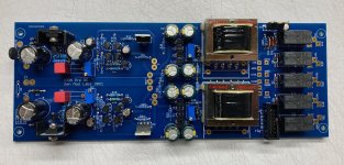
More progress. I like the Chrismas windings on the Cinemags, it shows the interleaving. I didn't have to do much trimming to get the Cinemag to fit over the edge of that one resistor, just clipped the corner with an x-acto. Now waiting for my chassis, and then to place a completion parts order once I see where everything fits.
Attachments
I’m actually waiting for an answer to this question as well. I will let you know when I hear back.I'm still waiting info about Muse package you asked about - is positive rail for relays common one?
Thank you for explaining #6 relay again!
Well I was going to add the iron Pre into the same enclosure as my DAC (which will have an arduino for control). I was going to plan to use it to switch the inlets on the Iron Pre. Arduino will not be running on the Iron Pre PSU. I guess I am a little confused on how to work out the switching logic as I collect parts for my balanced build. Want to make sure I have the parts I need.
Well I was going to add the iron Pre i
taking in account that your case may but also may not be applicable to anyone else's, best to open new thread in time
there you can present enough info, and I'll help you with details about Iron Pre
be it existing or slightly altered one (in future, positive relays rail being common)
well, it doesn't matter
as I see it, majority of digital circuits will include low side switches as logical and simplest, that calling that positive relays rail is common and negative (consequently tied to digital GND) is switched for each relay
I did my changes to Iron Pre boards (no changes in parts nor their designation) and it'll be digital-friendly from next batch
as said, necessary change to existing gen. of pcbs is minimal and trivial, to mate with any gizmo you have
taking in account that your case may but also may not be applicable to anyone else's, best to open new thread in time
there you can present enough info, and I'll help you with details about Iron Pre
be it existing or slightly altered one (in future, positive relays rail being common)
Will open a thread when I get closer to figuring it all out. I will get all the parts coming. Maybe hold off on all the relays until I am sure what I am doing. The arduino has 3.3V logic if that matters. Thanks.
Question about chassis...what size is it, or is it a range of sizes with custom iron pre face plate and rear plate?
Russellc
Russellc
See previous posts... 6L6, Gianluca, and IAIMH... There are two chassis. All details covered.
ya see how smart I am??
(don't tell anyone that I had fluffy sound first time feeding prototype with SE signal; was scratching my head for at least 5min)

(don't tell anyone that I had fluffy sound first time feeding prototype with SE signal; was scratching my head for at least 5min)
^ Dang you're fast. I deleted the pic / post because with the updated boards... the overall function is the same, but the switching is just a weeeeeee bit different. I'll post a pic with better wording in a sec.
🙂
🙂
- Home
- Amplifiers
- Pass Labs
- Iron Pre Essentials Kits For The DIYA Store - Register Your Interest