Congrats to @Zen Mod on launching the IronPre on the DIY Audio Store. Zen built an Iron Turtle with FineMET for me, and it's great. Anyone building the Iron Pre is also in for a treat.

Well, as Jim said in yesterday's BAF short note, site deserves all help we can give
besides, I can produce only what I can, while Greediness of Greedy Boyz is much greater, and - as Pa said - it's even better when it's dirt cheap!
just remember:
besides, I can produce only what I can, while Greediness of Greedy Boyz is much greater, and - as Pa said - it's even better when it's dirt cheap!
just remember:
Damn
Pair of HiNi Cinemagz is costing me more than SE kit, to get them in my Neck of Wood
(this is gentle nudgenudge)

What does schematic say for recommended VA rating? SE or Bal... using one or two transformers if bal?
Edited to add - someone did 15V previously, I believe. If you don't need the voltage swing, then that's your choice. ZM can confirm. Oh... and be sure about your relay operating voltage if applicable. That's all I can come up with, but MZM is master of all.
Edited to add - someone did 15V previously, I believe. If you don't need the voltage swing, then that's your choice. ZM can confirm. Oh... and be sure about your relay operating voltage if applicable. That's all I can come up with, but MZM is master of all.
we can count that xformers will have slightly higher secondary voltage than specced
try
you need at least 20Vdc rails after diodes to have steady 15Vdc after reg
that being worst case scenario, if having prolonged -10% voltage from the wall
try
you need at least 20Vdc rails after diodes to have steady 15Vdc after reg
that being worst case scenario, if having prolonged -10% voltage from the wall
Will i get away with using a 25va with 2 sec of 15v as i already have one.

So with a sore back I'm able to sit half an hour at a time and figured something out why my relays (channel relays) were not clicking:

I believe silkscreen orientation, and thus diode orientation of D5 to D9 is incorrect on my boards. So I will change orientation of diodes in place.
I have been able to reflow the boards, did not see anything weird. Are there points I can measure and compare with other half with regards to still persisting P3 offset at -28mv issue?
Should I try to swap the j74 between pos and neg half to see the behaviour persists?
It looks tricky to use a 7x2 pin header for a 5x2 pin application. If the key on the socket is inverted on the rotary switch board, then four of the wires will be disconnected on one end.
Edit: I take that back, it looks like 7x2 is correct. It's just that my header didn't hang off the edge of the board like that.
Edit: I take that back, it looks like 7x2 is correct. It's just that my header didn't hang off the edge of the board like that.
So with a sore back I'm able to sit half an hour at a time and figured something out why my relays (channel relays) were not clicking:
I believe silkscreen orientation, and thus diode orientation of D5 to D9 is incorrect on my boards. So I will change orientation of diodes in place.
I have been able to reflow the boards, did not see anything weird. Are there points I can measure and compare with other half with regards to still persisting P3 offset at -28mv issue?
Should I try to swap the j74 between pos and neg half to see the behaviour persists?
you have initial run boards, where negative is common for relay circuit
so, as not first one trying to assemble it, maybe really just your boards are having parts overlay all messed

now - I can bet that you misplaced ZD1 and ZD2
ZD1 - for your relays - must be 27V
ZD2 - gate protective - can be anything from 5V6 to 20V
check these
fastest way - 14pin header - as on your picture - 2 upper pins are Rly+, two lowest pins are Rly-
take DVM, you need to have 23 to 24Vdc between those
Should I try to swap the j74 between pos and neg half to see the behaviour persists?
if you're going to pull them out, why not test them?
it's always better to make a mess informed, than to make a mess blindly
before my herniated disk surgery tomorrow
hope everything went well?
24.4 dc between relay + and-, check.you have initial run boards, where negative is common for relay circuit
so, as not first one trying to assemble it, maybe really just your boards are having parts overlay all messed
now - I can bet that you misplaced ZD1 and ZD2
ZD1 - for your relays - must be 27V
ZD2 - gate protective - can be anything from 5V6 to 20V
check these
fastest way - 14pin header - as on your picture - 2 upper pins are Rly+, two lowest pins are Rly-
take DVM, you need to have 23 to 24Vdc between those
Now, taking board out of chassis PSU lines show now plus 9vdc with no change to P1 and -0.8v on negative rail. Guess I screwed the good Gemini. For ease of troubleshooting why don't I populate a new board with fresh parts? Measuring the parts in the meantime😉
Well, no more numbness and pain in the leg. I am a happy camper, just moving around feels like I'm 80! But thanks🙂hope everything went well?
moral of the story - do not mess with electronics while having spine totally ooked
(last 20 years living with exact problem, but still outa Op stage, luckily)
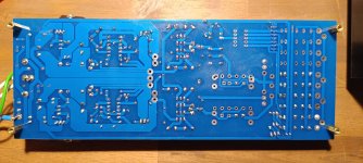
if repair is to commence - why not starting with proper pics of both upper and lower side of pcb?
(last 20 years living with exact problem, but still outa Op stage, luckily)
if repair is to commence - why not starting with proper pics of both upper and lower side of pcb?
Haha absolutely, I tried to use as little painkillers as possible but I realise what they did to me😉 luckily I can back down on them already.
Hope you can keep it that way with practice!
So upper side:
Gemini


Buffer

Lower side

Oh and I heard relay 1 clicking after reorienting d5. D6 and d7 will follow but first things first.
Edit: closup bottom side:

Hope you can keep it that way with practice!
So upper side:
Gemini
Buffer
Lower side
Oh and I heard relay 1 clicking after reorienting d5. D6 and d7 will follow but first things first.
Edit: closup bottom side:
Attachments
Last edited:
can't see anything else in this moment, but I can say that D5 to D9 must be oriented as per overlayOh and I heard relay 1 clicking after reorienting d5. D6 and d7 will follow but first things first.
if you don't believe me - test it - when you establish proper relay PSU voltage ( in range of 23Vdc), put red probe on IDC connector Rly+ pins, and black probe to (any) diode Anode ( non stripe end) and you'll see that anodes are on neg Rly leg
if you want that diode conducts current ( shortly before dying) instead of relay, feel free to orient them by your wish
now - "my relay is not clicking" .......
how exactly you tried energizing each relay?
if not with enclosed rotary switch and p[roper flat cable, you can do that connecting Rly+ pins with apropriate pins on IDC connector; +1 for Rly1, +2 for Rly 2 etc.
triple check positioning of all active and passive parts
most common mistakes are not following this simple logic:
all BJTs in positive rail are NPN, while mosfet is Pchannel (IRF9510)
all BJTs in negative rail are PNP, while mosfet is Nchannel (IRF510)
most common mistakes are not following this simple logic:
all BJTs in positive rail are NPN, while mosfet is Pchannel (IRF9510)
all BJTs in negative rail are PNP, while mosfet is Nchannel (IRF510)
@Robin De Wolf - Of course Omnipowerful ZM is correct.how exactly you tried energizing each relay?
if not with enclosed rotary switch and p[roper flat cable, you can do that connecting Rly+ pins with apropriate pins on IDC connector; +1 for Rly1, +2 for Rly 2 etc.
First - I hope you're well and recovering nicely.
Second - I will simply add a word of caution from <cough> experience. Be careful. I'd suggest choosing a way to do this such that you cannot short your PSU rails. The V+ and V- supply are both present on the 14-pin connection. I can say with certainly that accidentally touching them makes things go poof that you don't want to go poof. Perhaps this is an unwarranted caution... but just in case.
Thanks IAIMH, the troubleshooting is a very nice distraction from recovery inconveniences.
Of course, ZM is right😈. The other channel is working as it should.
Just for giggles:

Measurement between AC1 and AC2 should be 36 vac with my dual secondaries (2x15v) transformers? or 0VAC?
Of course, ZM is right😈. The other channel is working as it should.
Just for giggles:
Measurement between AC1 and AC2 should be 36 vac with my dual secondaries (2x15v) transformers? or 0VAC?
- Home
- Amplifiers
- Pass Labs
- Iron Pre Essentials Kits For The DIYA Store - Register Your Interest