further investigations to be reported!
during my tests for port 1 (in the smaller chamber of my test parallel 6th order bandpass box) I tried to replicate the seemingly "non-resonant" rectangular curved wall port of chamber 2, but it did not seem to be possible.
so I repeated the measurement of port 2, as reported previously in posts 52 and 53:
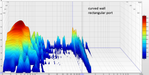
new measurement:
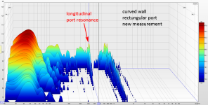
so, the longitudinal port resonance is still there.
I don't know exaclty why the previous measurements were so much "better". but I suppose it was just a coincidece...
by the way I realized that REW or my soundcard driver sometimes has glitches resulting in cracking sounds during the sine sweeps. If this happens the measurement is faulty and has some kind of severe comb filtering. I tried to increase buffer size and change from java to ASIO driver. still no final solution, yet.
during my tests for port 1 (in the smaller chamber of my test parallel 6th order bandpass box) I tried to replicate the seemingly "non-resonant" rectangular curved wall port of chamber 2, but it did not seem to be possible.
so I repeated the measurement of port 2, as reported previously in posts 52 and 53:
previous waterfall plot:for confirmation here are the waterfall plots:
View attachment 1206564View attachment 1206563View attachment 1206562

new measurement:

so, the longitudinal port resonance is still there.
I don't know exaclty why the previous measurements were so much "better". but I suppose it was just a coincidece...
by the way I realized that REW or my soundcard driver sometimes has glitches resulting in cracking sounds during the sine sweeps. If this happens the measurement is faulty and has some kind of severe comb filtering. I tried to increase buffer size and change from java to ASIO driver. still no final solution, yet.
influence of interior port opening position
rectangular curved wall port in chamber 2 is located directly below the upper enclosure wall.to investigate whether the output of enclosure resonance having a pressure maximum at the walls can be reduced I modified the port to be inclined:
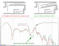
section and measurement should be self-explanatory.
while not very strong, there is some positive acoustic effect if the interior end of the port is not located next to enclosure walls.
also see post 23 with measurement of port mounted to the in- and outside!
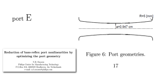
port geometries resulting in similar (same) helmholtz frequency:
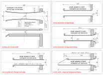
and respective impedance measurements:
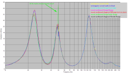
the "hard edge port" has highes losses as can be seen in the impedance graph (cyan): impedance peak at 23 Hz is lower and impedance minimum at 35 Hz is higher than the rest!
in case of my "curved wall port" with cross section varying between 12,6 and 18,2 cm2 I got the same result while simulating a port with same length and the arithmetic average cross section: (12,6 + 18,2) / 2 = 15,4 cm2
I guess for different port geometries the effective (corresponding) cross section may also be different!
@b_force - just as you predicted in post 51!
I think it's more around 15.4 cm² (probably slightly lower)
Last edited by a moderator:
chamber 1 port variants
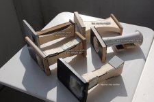
all port variants have the same (or nearly the same) cross sections: 18 cm² at the ends and 8 cm² in the center, resulting in an arithmetic average of 13 cm² (similar to the original cardboard tube with 4 cm diameter).
I did not sand and smoothen the plywood ports except for the roundovers. this resulted in more chuffing with high air speeds.
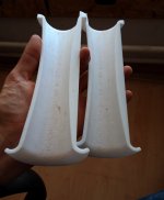
I printed the 3d-printed port in two halves to be able to sand and smoothen the surface. this resulted in very low chuffing!
also, the very flat and wide port (14 * 127 mm) has the interior end opening nearly to the side walls of the enclosure (140 mm). thus the enclosure width resonance output increased!
Last edited:
If I correctly understand the Roozen paper cited here - https://www.diyaudio.com/community/threads/port-measurement.380629/post-6879912 - those resonances are generated within the port itself and related to its length instead of passing resonances generated within in the enclosure. This corresponds well with the measurements, a large resonance at ~1 kHz with a ~6" port. Followups I saw looking at damped perforated 3-D printed ports may have missed a suspected critical element. The printed port wall perforations looked like square cut >1/4" deep holes. Chuffing at high velocity isn't surprising. With material that deep tapering the inside hole profile, at minimum longitudinally, to minimize sharp disruptive edges in the direction of flow is worth consideration.enclosure resonance
My next trials planned to replace the already thin wall and file cleaned Home Depot plastic ports (drain pipe adapters) with even thinner wall brass but the enclosures have since been repurposed for a sealed test build.
thanks @rdf for pointing me to the roozen paper and to your thread!
I was not aware of both - very interesting and valueable!
the paper describes scientifically some of my amateurish explanations.
"figure 3" and "figure 4" in the paper seen somewhat similar to my "sketch" in post 46 and my photographs in the previous posts.
it also makes a clear distinction of boundary layer turbulence and unsteady flow separation and states that the unsteady flow separation (i called it "port stalling") is more critical for small diameter ports.
this measurement was done with rather low volume (1 V rms), so turbulence resonances are not yet excited. however, all resonances of enclosure and ports (even room resonances in a very low degree due to 10 cm measurement distance) can be seen.
for an overview of resonances see my post #19!
these resonances can also be simulated with hornresp, for example. hornresp allows only one main enclosure dimension, but changing enclosure length and/or port length allows to identify precisely what resonance is created by enclosure or port.
i will upload the measurement graph.
thanks again!
I was not aware of both - very interesting and valueable!
the paper describes scientifically some of my amateurish explanations.
"figure 3" and "figure 4" in the paper seen somewhat similar to my "sketch" in post 46 and my photographs in the previous posts.
it also makes a clear distinction of boundary layer turbulence and unsteady flow separation and states that the unsteady flow separation (i called it "port stalling") is more critical for small diameter ports.
while the roozen paper refers to resonances generated by turbulence ("chuffing" which I also measured see post 26) I referred to resonances visible in a sine sweep frequency measurement of port output.those resonances are generated within the port itself
this measurement was done with rather low volume (1 V rms), so turbulence resonances are not yet excited. however, all resonances of enclosure and ports (even room resonances in a very low degree due to 10 cm measurement distance) can be seen.
for an overview of resonances see my post #19!
these resonances can also be simulated with hornresp, for example. hornresp allows only one main enclosure dimension, but changing enclosure length and/or port length allows to identify precisely what resonance is created by enclosure or port.
i will upload the measurement graph.
thanks again!
some corrections - I apologize!thanks @rdf for pointing me to the roozen paper and to your thread!
I was not aware of both - very interesting and valueable!
it was your post in jimbone's thread.
and I just realized that you already mentioned both thread and paper here in this thread. apparently it was too long ago for my brain!
Last edited:
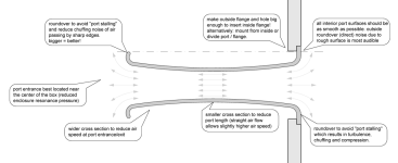
as a recap (mostly for myself) here ist the reasoning behind the considerations for the 3d printed port:
the weakest point of the port is at both ends or other abrupt port shape changes. the air flow shall be kept laminar to avoid any turbulence leading to excitement of longitudinal port resonance and air noise = chuffing and compression. in other words: we need a efficient pressure-to-velocity and velocity-to-pressure-transformer. this becomes mostly problematic with high air speeds.
thus:
3d printed shells of port prior to sanding, smoothing and coating:
(Sorry picture got lost)
I am still collecting and organizing measurement data to be posted here regarding: max air speeds before chuffing, difference (or lack of) between round, rectangular and slot ports, experiments with absorbers (center and 1/4 length), including a thin elastic layer between port and absorber, trying to replicate the low Q resonance of the straight port in the roozen paper...
the weakest point of the port is at both ends or other abrupt port shape changes. the air flow shall be kept laminar to avoid any turbulence leading to excitement of longitudinal port resonance and air noise = chuffing and compression. in other words: we need a efficient pressure-to-velocity and velocity-to-pressure-transformer. this becomes mostly problematic with high air speeds.
thus:
- the entrance and exit of port should be rounded.
- the air velocity should be reduced at entrance and exit (or even the complete port) to avoid non-laminar airflow at air direction changes. this can be achieved by increasing the cross section surface of the entire port or at both ends.
- narrowing of port in the middle does not cause any additional chuffing, as long as it is not extreme. advantage of narrowing: port can remain smaller/shorter.
- all interior surfaces of port should be as smooth as possible.
3d printed shells of port prior to sanding, smoothing and coating:
(Sorry picture got lost)
I am still collecting and organizing measurement data to be posted here regarding: max air speeds before chuffing, difference (or lack of) between round, rectangular and slot ports, experiments with absorbers (center and 1/4 length), including a thin elastic layer between port and absorber, trying to replicate the low Q resonance of the straight port in the roozen paper...
Last edited:
I found that stiffness to weight is important for the walls when using a layer damping approach. You want stiff to minimise movement, but added mass increases inertia and makes damping more difficult. So stiffness with minimal mass and a constrained damping layer like acrylic or butyl.
Hundreds, which actually makes digging out an ideal comparison kind of tricky. I'll see if I can find a good example later.
Here is 3 plots taken from within the port.
Port is in a very small cabinet about 2.5L and port is a slot port style with length about 20cm.
Purple = 9mm MDF construction
Yellow = 6mm port wall 3D printed
Blue = 6mm port wall made of 2x 3mm layers with adhesive between

I later found the cabinet side and back was resonating around 400Hz which I think is part of what we see with the the lower freq. unwanted spikes. Changing the port affects that too because of course it is all a system working together but I don't think it is initially caused by the port. Thinking about it in hind sight, the MDF port was glued in across the side walls acting as a brace, while the 3D printed ports were fixed with silicone so I could remove them again. All these factors will have an effect. Closing the port I still see a wiggle in that 400Hz area in the over-all speaker response. That higher freq. spike around 800Hz is for sure the port alone as it goes away in the system response when the port is closed.
You can achieve similar reduction of the unwanted resonances by adding small holes to the port and damping them, but I found that very significantly increased chuffing noise.
Port is in a very small cabinet about 2.5L and port is a slot port style with length about 20cm.
Purple = 9mm MDF construction
Yellow = 6mm port wall 3D printed
Blue = 6mm port wall made of 2x 3mm layers with adhesive between
I later found the cabinet side and back was resonating around 400Hz which I think is part of what we see with the the lower freq. unwanted spikes. Changing the port affects that too because of course it is all a system working together but I don't think it is initially caused by the port. Thinking about it in hind sight, the MDF port was glued in across the side walls acting as a brace, while the 3D printed ports were fixed with silicone so I could remove them again. All these factors will have an effect. Closing the port I still see a wiggle in that 400Hz area in the over-all speaker response. That higher freq. spike around 800Hz is for sure the port alone as it goes away in the system response when the port is closed.
You can achieve similar reduction of the unwanted resonances by adding small holes to the port and damping them, but I found that very significantly increased chuffing noise.
Last edited:
Looking back at my data I also tried a variable thickness walled port. I didn't go that route while I killed off the 800Hz resonance because of the big ~400Hz spike, but perhaps I should revisit this method with the port fully glued in to the cabinet and the back panel braced....
There is always something more to try but at some point we need to move on.

There is always something more to try but at some point we need to move on.
What do you mean by the mic is in the port? Is it touching the port or speaker in any way? I could see that being a problem. Changing construction materials could be a confounding factor also. There will be a difference between the 3D printed and MDF version simply due to the surface roughness, unless finished the 3D port smooth?
I used a small mic that was inside the port about 5cm and a stiff wire it so it doesn't touch.
There are fewer confounding factors between the solid 6mm, 6mm layer damped and variable thickness ports. Thay all have the same internal geometry and are 3d printed.
I didn't do these experiments with the intention of sharing the results, but rather to optimise a specific build. I'll be happy to see any follow up tests anyone else does!
BTW, chuffing from surface roughness seems to be rather independent of resonances. Instead that produces wide-band noise in the >1khz range.
I don't follow why you want to measure inside the port, unless you want to measure just the behavior of the mode itself.I used a small mic that was inside the port about 5cm and a stiff wire it so it doesn't touch.
But losses can be just measured outside of the port and an easier method is in combination with impedance plots.
- Home
- Loudspeakers
- Multi-Way
- Investigating port resonance absorbers and port geometries
