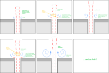
exactly.flow separation such that there are recirculating zones
here is a comparison i made today - it's quite a challenge to take good, meaningful pictures!

(Edit: same shutter speed for both photos!!)
as far as I know the port has high velocity and low pressure.
so we need an acousic transformer to couple the high velocity to pressurize the room outside the port.
otherwise we will just waste a lot of energy into unwanted friction between air layers and differences in air flow depending on flow direction.
by the way:
the bigger the surface of the port, the smaller the velocity and in addition the better the ratio between surface and circumference.
and of course this does not only apply to ports but also to loudspeaker drivers!
I am just starting to realize how much impact this effect may have.
Last edited:

ok, I made a quick master's degree in fluid particle photography....
here is the comparison between a hard edge port and a sloped, rounded edge port.
both were taken with the exact same parameters:

of course there is some particle movement due to them being sprayed, but i think the difference is quite obvious.
here is the comparison between a hard edge port and a sloped, rounded edge port.
both were taken with the exact same parameters:
- 35 Hz at 8 V rms
- 12,6 cm2 port cross section (smallest cross section for the sloped port)
- 1/400 shutter speed
- water mist produced with a water sprayer for plants, resctricted in height with two cardboard pieces ~2 cm high, to allow a "cross section" flow picture.
of course there is some particle movement due to them being sprayed, but i think the difference is quite obvious.
With a bigger diameter, the boundary layer effect is a lot less severe.the bigger the surface of the port, the smaller the velocity and in addition the better the ratio between surface and circumference
So there is naturally a lot less resistance.
With any transition in fluid dynamics, flares are a must, or you will get impedance jumps, causing vortices.
edit: that also counts for abrupt corners etc.
I would get one of those fog machines, you can often buy them for really cheap 2nd hand.
Last edited:
Use ultrasonic humidifier to make ultrafine particles. Use a laser sheet (glass rod cylinder lens and green laser pointer) to make the light slice the plume.
https://a.aliexpress.com/_mq2Hrim
https://a.aliexpress.com/_mrPGLly
https://a.aliexpress.com/_mKp7dDU
You can get a lot of stuff that would have cost thousands in the past for fluid viz research for a few dollars nowadays.
https://a.aliexpress.com/_mq2Hrim
https://a.aliexpress.com/_mrPGLly
https://a.aliexpress.com/_mKp7dDU
You can get a lot of stuff that would have cost thousands in the past for fluid viz research for a few dollars nowadays.
If you want to take this to the next step, use a pulsed laser (more expensive) and make a circuit to phase lock the speaker signal to the laser pulse. Then vary the phase (delay) between the speaker and laser and you can see the time evolution of the pulse.
I actually did this for a 2D jet (a long slot) that generated a recirculating eddy that moved through a burning flame interface. I used a speaker woofer driver as the device to pulse the fuel/air jet. I used a frequency doubled dye laser to excite the OH molecule in the flame to visualize the flame interface. It was a fun experiment.
I actually did this for a 2D jet (a long slot) that generated a recirculating eddy that moved through a burning flame interface. I used a speaker woofer driver as the device to pulse the fuel/air jet. I used a frequency doubled dye laser to excite the OH molecule in the flame to visualize the flame interface. It was a fun experiment.
Could you create a setup where you can photograph the port exit in such a way as to mimic the COMSOL sims in the Bezzola paper? Looks like they identified a good mechanism of particle velocity contour at port exit.
Or someone with COMSOL could recreate their sim. I have COMSOL but no idea how to use it.
Or someone with COMSOL could recreate their sim. I have COMSOL but no idea how to use it.
Last edited:
port variants
there were some more variants and tests, but these are the most interesting three:


and here come the numbers!

note that while the percentage for the port resonance chuffing noise seems to be small this sound - if present - is very clearly noticeable and quite annoying.
see my table regarding subjective chuffing noise perception.
i sanded and smoothed the straight rounded port adapter plate after routing the roundover, this improved chuffing and noise very much.
the rectangular curved wall port adapter plate was smoothed with modeling clay and painted with matte primer.
as you can see the rectangular port with curved walls performs best in most disciplines, most noticeable the very limited port resonance chuffing (also reflected in the %N -- noise numbers) and the minimal H3 distorsion and the limited compression.
the possible curvature was limited here due to the restricted space for mounting the port adapter plate.
more curvature may lead to even better results - see @augerpro 's "augerport" and the references he mentions!
well photos I took were challenging enough to do!to mimic the COMSOL sims in the Bezzola paper?
but surely it would be interesting to get even better pictures. I will give it a try!
anyone like to know how to test the ports of your bass reflex loudspeakers for port stalling?
do you need certainty to always keep your system below the critical angle of attack?
the simple and effective method you have been waiting your whole life!!
this is the setup:

just use a thin paper mounted about 5 cm in front of the port mouth.
next you set your computer or sine generator to play a sine tone just at the tuning frequency of your loudspeaker.
now watch the paper as you increase the level of your amplifier!!
here are examples of three different ports, conveniently linked to the data in the post above:

everything is ok as long as your paper stays vertical (of course vibrating) or comes near the port mouth due to the laminar air flow along the speaker walls. it's even ok if the paper is being sucked towards the port.
if however the paper gets blown away from the port you either have turned the amp too loud or (sorry to say so) your port "sucks" ... eeer: blows!
as you can see the straight hard edge port starts "blowing" from 1 V up.
this is a sign for turbulent air flow. NOT GOOD!
it is also reflected in the data: compression starts from low level and increases steadily. same with resonance chuffing and noise.
the rounded port behaves much better: the paper only gets blown away at 8 V. this can be seen in the data: compression is nearly zero only to start rising after 4 V. same with port resonance chuffing, noise and HD.
finally the curved wall rectangular port: before "blowing" at 16 V the paper is attracted by high velocity laminar flow. performance in specifications is best!
do you need certainty to always keep your system below the critical angle of attack?
here comes SHePoST!
Stv's Helmholtz Port Stalling Testthe simple and effective method you have been waiting your whole life!!
this is the setup:
just use a thin paper mounted about 5 cm in front of the port mouth.
next you set your computer or sine generator to play a sine tone just at the tuning frequency of your loudspeaker.
now watch the paper as you increase the level of your amplifier!!
here are examples of three different ports, conveniently linked to the data in the post above:
everything is ok as long as your paper stays vertical (of course vibrating) or comes near the port mouth due to the laminar air flow along the speaker walls. it's even ok if the paper is being sucked towards the port.
if however the paper gets blown away from the port you either have turned the amp too loud or (sorry to say so) your port "sucks" ... eeer: blows!
as you can see the straight hard edge port starts "blowing" from 1 V up.
this is a sign for turbulent air flow. NOT GOOD!
it is also reflected in the data: compression starts from low level and increases steadily. same with resonance chuffing and noise.
the rounded port behaves much better: the paper only gets blown away at 8 V. this can be seen in the data: compression is nearly zero only to start rising after 4 V. same with port resonance chuffing, noise and HD.
finally the curved wall rectangular port: before "blowing" at 16 V the paper is attracted by high velocity laminar flow. performance in specifications is best!
Last edited:
You say that the surface area of the rectangular is the same, but with the dimensions you have atm, I doubt if that is true acoustically.
I think it's more around 15.4 cm² (probably slightly lower)
You should be able to see that with the impedance measurement from the woofer.
It can be actually VERY tricky to have the same amount of airflow when the impedance (and therefor the cone excursion) is not quite the same.
Generally speaking, rectangular shapes are worse, not better.
But in this case, the shape is very different, so I think the surface area is a bit bigger.
Do you also have a measurements of a 35.5x35.5 mm square port?
A rectangular port (slotted port) would also be very interesting to see.
Say something like 18 x 70mm or even 12 x 105mm.
Btw, if it's about port losses, there is an easier method to this madness.
Something we did over 15 years ago during thermodynamics experiments at the university.
You just fill some (big) volume (a bucket or something) with water and let the water out from these ports.
At the same time you count the time (stopwatch) as well as the volume you of water (easier just to measure the weight)
You will also very quickly see that with flaring ports the stream of water reaches a much bigger distance.
Obviously this doesn't say much about compression etc.
Although fluid dynamics works slightly different for air vs water, it's still a decent indication of how well a port is optimized.
well I took the narrowest width of 45 mm, multiplied by 28 mm makes 12,6 cm².I think it's more around 15.4 cm²
of course it is debatable, whether i should use the medium width or even the lagest one.
but impedance measurements very clearly showed correct resonance peaks (or dips). I will post impedance plots later!
I have to add that while the round ports were located in the middle area of the box, the rectangular was next to a box wall.
BOXSIM allows to simulate this and gave a reduced port length (minus 2 cm) for a rectangular port with continuous cross section 45 x 28 mm.
with the curved wall port the tuning of chamber 2 was slightly high, so i added 2 cm again at the interior end of the port.
I also have to add that the rectangular shape was mostly due to manufacturing restrictions. I did not want to 3d-print a 28 cm long, very narrow port and having to smooth the interior surface.
(give me some time and have a look into the next posts where i will show the difference between a routed roundover vs. additional sanding and smoothing. smooth surface is essential, mostly at the port mouth!)
I might try printing it in 2 half shells and gluing it together afterwards. but I actually am glad that the simple bent plywood port behaves so good - I will definitely use this method again!
but anyhow, my interest was more to see how port forms generally behave.
how to correct them for identical tuning will be the next challenge!
by the way - my initial goal were port resonances....
here are the three port responses:

port length resonance is clearly visible at around 550 Hz for straight ports. (slightly higher for rounded port! if you want to calculate yourself make sure to consider end correction)
but wait .... where is the port resonance for the curved wall port??
well, it's gone!!
so the curved wall port not only provides the best port flow behaviour but it also has the least pipe resonance!
GREAT!!
I honestly did not expect this.
Last edited:


is a perfectly smooth sufrace (at the port mouth) really necessary?
well...


left: just routed with roundover bit 9,5 mm radius. right: additional sanding and smoothing out remaining edges with 240 final sanding.
differences in HD spectrum are not entirely clear to me.
maybe I did not wait long enough with one of the screenshots and the averaging was still ongoing...
well...
left: just routed with roundover bit 9,5 mm radius. right: additional sanding and smoothing out remaining edges with 240 final sanding.
differences in HD spectrum are not entirely clear to me.
maybe I did not wait long enough with one of the screenshots and the averaging was still ongoing...
editing time over ...
in case it is not obvious: the smoothed surface removes most of the noise from 2 kHz up!
in case it is not obvious: the smoothed surface removes most of the noise from 2 kHz up!
impedances

the "high loss" straight hard edge port is also recognisable in the impedance plot!
I have to admit, the rectangular port makes the box tuning indeed still slightly (2 Hz) higher than the rounded one!
when simulating with hornresp the port surface increases to 14,10 cm².
spot on!!15.4 cm² (probably slightly lower)
(the strange dip in the traces at 50 Hz is a mains buzz in my amp... I'll have to get rid of that sometimes!)
You should have warned me .... 😱Use ultrasonic humidifier
These thing get addictive!
Now i have yet another project to work on
😊
Thanks for the great suggestions!
here is the response graph indicating how the helmholtz resonator (absorber) at half the port length and tuned to the port longitudinal resonance interacts with the port:Bad news is: the absorbing resonator interacts with the port and creates a new (lower frequency, unfortunately) resonance. This phenomenon seems to get stronger for shorter ports.

the absorber indeed absorbs the longitudial resonance of ~560 Hz BUT:
a new stronger and even lower resonance is created, apparently combining longitudinal resonance with helmholtz absorber.
it's now at 410 Hz which is worse, because near to the useful output of the port. in addition the useful port output is slightly reduced (about -1 dB)
this resonance can be dampened with fibrous material in the small helmholtz absorber at the expense of another reduction of useful output (about -2 dB).
so in short:
it makes much more sense to use a less resonating port shape (see post #52, #53, avoid straight tubes without big rounded flanges!) instead of installing small resonators to absorb port resonance.
it may be sensible with very long ports, though (see the first posts in this thread).
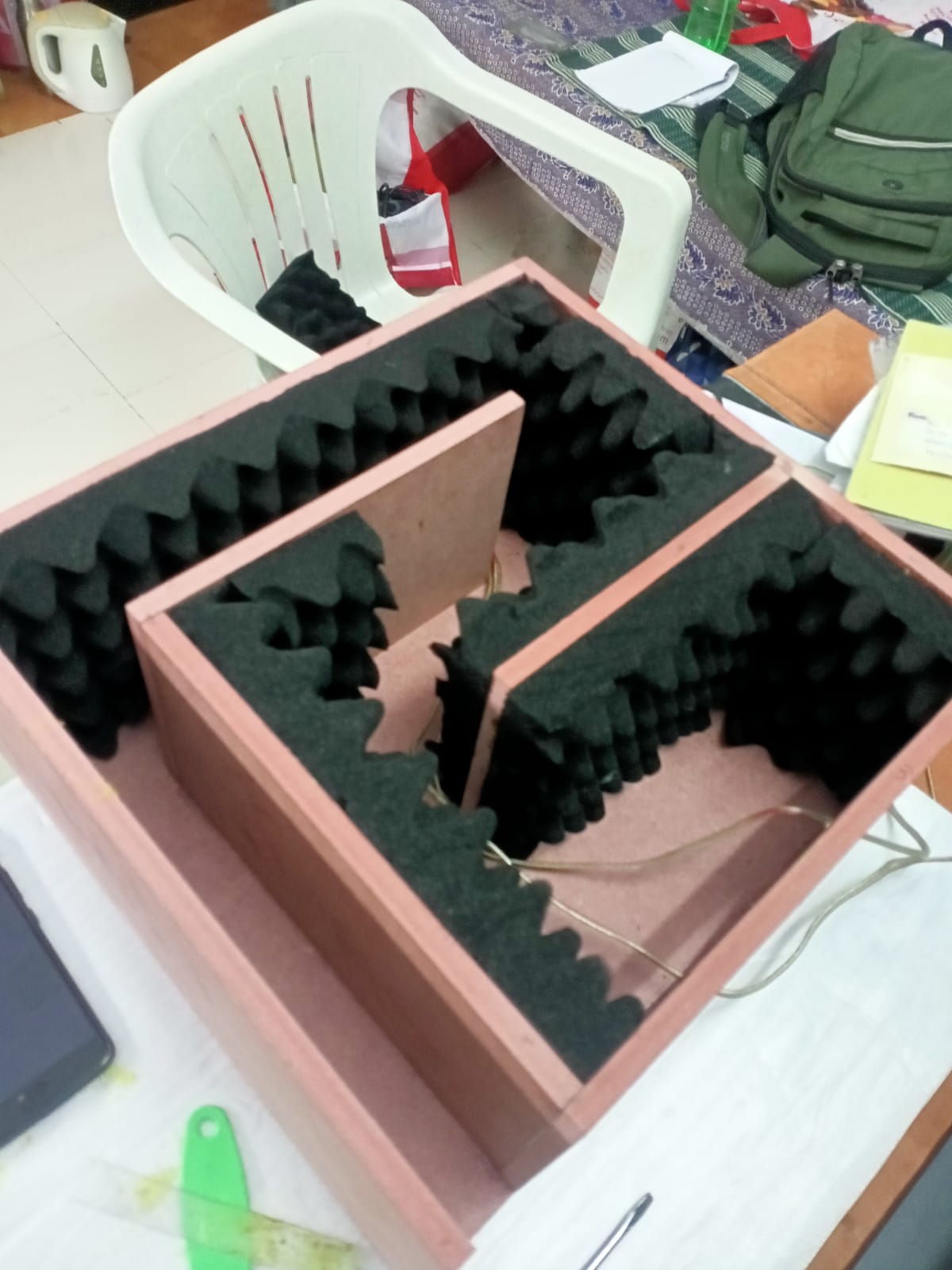
This might be one reason tapered TL speakers (like PMC) have a very clean bass. The exit terminus is relatively large so velocities are low. The entire TL walls are lined with damping material and there is stuffing on the closed end, plus there are sharp corners that act to filter out these higher frequency peaks. Of course, it is longer.
All of this can be modeled and the application of corners, damping etc all show an improved lack of higher frequency peaks.
https://www.diyaudio.com/community/...ired-tl-monitor-with-dc130a-and-dc28f.281778/
These are predictions using Akabak…
Light stuffing - notice resonance peaks:

Impedance with light stuffing:

Moderate stuffing:

Impedance with moderate stuffing:

Here is what the inside looks like (example made by Sumeshak) with walls lined with eggcrate foam:
All of this can be modeled and the application of corners, damping etc all show an improved lack of higher frequency peaks.
https://www.diyaudio.com/community/...ired-tl-monitor-with-dc130a-and-dc28f.281778/
These are predictions using Akabak…
Light stuffing - notice resonance peaks:
Impedance with light stuffing:
Moderate stuffing:
Impedance with moderate stuffing:
Here is what the inside looks like (example made by Sumeshak) with walls lined with eggcrate foam:
Last edited:
Hello All,
Interesting thread.
If you look over at audiosciencereview.com/forum/index.php?reviews/ for bass reflex speaker reviews every one has a plot with the microphone near the reflex port. Every one has port noise and resonate type distortions.
Looks like bass reflex ports are at best a medium to poor compromise to reach lower frequency output. More thoughts later, going to the beach.
Thanks DT
- Home
- Loudspeakers
- Multi-Way
- Investigating port resonance absorbers and port geometries