NEW - BETA! thread index at the end of this post!
When planning, simulating, building and measuring bass reflex enclosures for 2-way speakers one difficulty is dealing with port resonances in the midwoofer’s passband.
I thought it should be possible to absorb resonances with Helmholtz resonators in/at the bass reflex port.
Obviously I am not the first to come up with this idea, but I also didn’t find very much about it on the internet.
Thus I decided to make my own measurements, see the following posts!
I had a quick scan through this thread with the search tool but did not see any mention of the simple, easy solution to the very real problem of of tube resonances that fall in the midrange region and are easily excited by a mid-bass driver.
Just put the port(s) on the rear panel instead of the front! Yes, really, that's all you need to do. Nothing fancier or more scientific needed.
The speakers I currently use had a port on the front initially and experienced the same issue - which can be particularly nasty when the port is fairly close to the driver.
The output from the front port at its Helmholtz resonance (approx. 600Hz from memory on these particular speakers) was strong enough that it caused an obvious and fairly significant dip and peak in the measured midrange response due to the the summing and cancellation with the direct output from the driver around the resonance of the tube. Subjectively it added significant harshness to the midrange.
I then added another port to the rear of the cabinet so I could alternatively block either the front or rear port, keeping the same bass alignment while shifting the exit location of the spurious resonance, and did a lot of listening tests as well as measurements, and the conclusion was clear:
When the port was on the front there was significant harshness in the midrange due to the resonance causing both a peak and dip in the summed far field response, and the change in response was very obvious in far field measurements.
With the port on the rear all audible traces of the resonance are gone, and all measurable traces of the peaks and dips are gone as well - in terms of the midrange, measuring 1-2 metres in front of the speaker there was NO difference in the midrange with either both ports blocked or only the rear port open.
I later permanently removed the front port, gluing a wood block in place to fill the hole and re-laminated the front panel so it now looks like there was never a port in the front, in fact it has two ports on the rear now to increase the cross sectional area for other reasons. (The original port diameter was a bit too small to avoid chuffing with higher levels of bass)
Why does it work ? Pretty simple really - unless your speaker is very narrow, the Helmholtz resonance of the port is likely well above the baffle step frequency of the cabinet - thus it will not easily radiate around the cabinet because the rear baffle is is acting as a baffle to constrain that unwanted radiation to the rear 180 degree sector of the speaker. In my case the resonance was at about 600Hz but the baffle step frequency is around 300Hz.
In theory it could bounce off a wall behind the speaker and make its way into the room but it is so delayed (relative to the direct radiation from the driver) and attenuated by then that it doesn't show in any measurements and isn't subjectively audible.
Another benefit of not putting the port on the front is you remove an unnecessary diffraction edge from the front panel. If you put a traditional non-flared port on the panel close to a mid-bass driver you've just added a large discontinuity right next to the driver that is probably worse than the cabinet edge. Why do this when it can be put on the rear panel ? Even if you flare the exit of the port you still have a big hole in the panel next to the driver. Just not a good idea IMHO.
There's so many good reasons to put ports on the rear panel of a speaker instead of the front and so few reasons not to that it surprises me that more people don't do it. I will never build another speaker with ports on the front.
I fully agree!Just put the port(s) on the back panel instead of the front!
But anyway I was interested in port resonances and whether it's possible to tame them.
And it may be handy just in case you would like speakers directly on the back wall with ports on the baffle, for example.
Edit: just found this in post #212, writing about optimizing a pair of small loudspeakers:
I will install new optimized ports on the back, a new baffle with CNC-cut waveguide, optimized crossover, oak veneers on the sides ...
Last edited:
Needing to push the speakers right up against a wall is the only reason I can think of not to put the ports on the rear, but if they're more than a few inches out it's fine, so the vast majority of medium to large free standing speakers will never have this issue. (Small bookshelf speakers that are actually on a bookshelf, yes, you could make a case for not doing it there)
While I'm sure you can damp the high frequency Helmholtz resonance in the tube, it's going to be difficult to do so without adding excessive losses to the desired low frequency Helmholtz resonance of the box that the port is there for in the first place. It doesn't take much resistive damping in a port to erase most of the benefits of going Bass Reflex in the first place so I shy away from trying to do anything like that. (I'm not a believer in "lossy" Bass reflex alignments)
It's the same reason you would normally never stuff a Bass Reflex cabinet, only line the walls.
Another advantage of the rear port that I forgot to mention is that it doesn't just suppress the Helmholtz resonance of the tube itself, it also hides any other spurious modal resonances inside the cabinet such as harmonics of internal axial resonances etc. Some of those can make their way out of a port as well and become audible.
If you have a strong axial resonance inside a cabinet including harmonics of it that you can't suppress because you can't stuff a bass reflex cabinet, they are not necessarily audible on the outside as there are only three ways they can escape to be heard:
1) By flexing the walls and using the walls as a sounding board - solution, bracing the walls, mechanical damping, heavier walls etc.
2) By re-radiating back through the cone of the driver (not much you can do here except use a thicker cone)
3) By radiating out a port - put the port on the rear panel.
As I said, I will never build another speaker with ports on the front, ports on the rear measures better, sounds better and (IMHO) looks better as well. It's just a no-brainer to me.
You should read through the entire thread, if you want to know what i (and others) propose to solve the issue.it's going to be difficult to do so without adding excessive losses to the desired low frequency Helmholtz resonance of the box that the port is there for in the first place.
I did several tests also addressing the issue of enclosure resonances exiting the port.
Anyway, thanks for your very practical suggestions!
Last edited:
Depends on the portport to the side?
😊
chuffing noise (if there is any) will me more audible from a side port than a back port.
Port resonances will not be excited by music signals up to 200 Hz (unless the port is very, very long).
Probably better than the front, (I haven't tried it) but not as good as the rear. The main way the rear port suppresses unwanted midrange resonances is due to the baffling effect of the rear panel. It probably depends a bit on whether the cabinet is wide and shallow (traditional shape) or narrow and deep (more modern) since the relative baffle sizes change. My cabinets are wide and shallow so the rear panel is much larger than the side panels.How about a port to the side? I have one box like that, but it is used below 200 Hz only ATM.
Hi @pelanjDepends on the port
i guess that statement above does not really help much, so here is my preliminary suggestion for a best behaving port geometry (post #320, 3d-printed in two halves to allow sanding and smoothing on the interior surface!).
Here is how the port is being inserted into the enclosure hole.
In post #338 you find a corresponding straight tube port leading to the exact same tuning.
I am still investigating the minimum dimensions that allow a good bass reproduction.
As far as i understand the limit is mainly depending on the particle displacement distance which in turn depends on tuning frequency and max desired output.
The critical areas for displacement are the port terminations not the high speed center, which may seem counterintuitive.
Generally the central diameter (only 2 cm for my test port, allowing clean bass output at 100 Hz and 8 V input) can be surprisingly small and results in a very short port with the big advantages of
- reduced space requirements,
- low transmission of enclosure resonances (see response graph)
- low resonance tendency and (most important) ...
- ... very high port length resonance (mode) frequency, preferrably far outside the useful woofer bandwidth.
All this is achieved without useful helmholtz resonance loss (0,1 dB compression between 1 and 8 V input, that is far below my measurement tolerances).
Also, chuffing noises are very low (or even absent, chuffing/spectrum measurement) with this geometry port.
as I am still working on this research my "ideal" port geometry may still change!
Last edited:
I am working on a synchronized reduced speed sound for my slow-motion-captures.
this is getting quite interesting, because in contrast to the real time analyzer (averaged sound pressure over time) it will be possible to distinguish different chuffing/resonance effects during the oscillation cycle.
as the slow-motion capture is only possible with disabled sound I need to find a way to synchronize sound and video.
I think the following method should be viable, although it is probably not perfectly exact.
but anyhow, I only have 3-4 frames per oscillation cycle, so it may not be that critical.
I used a paper sheet and let it slap on the port opening with the 35 Hz tone at rather high level:
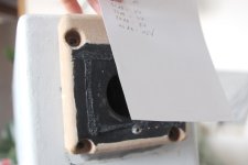
then I recorded the signal, opened it in a wave editor, zoomed in and tried to analyze it:
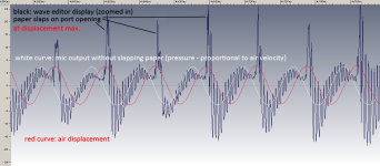
So in the wave editor the positive peaks correspond to the inward directed air velocity.
(let me know if you think there is something completely wrong about my assumptions!)
I'll insert a piece of slowed down sound into the next videos!
while looking at the waveforms in the editor I realized another somewhat alarming effect:
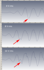
the image shows the starting cycles of a 35 Hz REW sine tone, just after clicking the "play" button.
at 8 and 16 V the driver apparently is clipping quite hard during the first high level cycle.
Intuitively I think this makes sense: how should a resonator build up enough pressure to counteract the high excursion of a diaphragm, if it was not (slowly) excited before?
so, if my assomption is correct, a helmholtz resonator can protect a driver from high excursions, but that is only valid for later cycles of a longer lasting tone.
also, speaking of driver overexcursion risk for bass reflex enclosures only below tuning frequency may not entirelly be correct. there is a risk even for the tuning frequency!
maybe this is common knowledge - but for me it was not, until now!
Edit:
What makes things even worse is that it happens only at one of the firsts cycle peak. One may not even notice it, but the voicecoil could already be hitting the magnet back plate!
this is getting quite interesting, because in contrast to the real time analyzer (averaged sound pressure over time) it will be possible to distinguish different chuffing/resonance effects during the oscillation cycle.
as the slow-motion capture is only possible with disabled sound I need to find a way to synchronize sound and video.
I think the following method should be viable, although it is probably not perfectly exact.
but anyhow, I only have 3-4 frames per oscillation cycle, so it may not be that critical.
I used a paper sheet and let it slap on the port opening with the 35 Hz tone at rather high level:

then I recorded the signal, opened it in a wave editor, zoomed in and tried to analyze it:

So in the wave editor the positive peaks correspond to the inward directed air velocity.
(let me know if you think there is something completely wrong about my assumptions!)
I'll insert a piece of slowed down sound into the next videos!
while looking at the waveforms in the editor I realized another somewhat alarming effect:

the image shows the starting cycles of a 35 Hz REW sine tone, just after clicking the "play" button.
at 8 and 16 V the driver apparently is clipping quite hard during the first high level cycle.
Intuitively I think this makes sense: how should a resonator build up enough pressure to counteract the high excursion of a diaphragm, if it was not (slowly) excited before?
so, if my assomption is correct, a helmholtz resonator can protect a driver from high excursions, but that is only valid for later cycles of a longer lasting tone.
also, speaking of driver overexcursion risk for bass reflex enclosures only below tuning frequency may not entirelly be correct. there is a risk even for the tuning frequency!
maybe this is common knowledge - but for me it was not, until now!
Edit:
What makes things even worse is that it happens only at one of the firsts cycle peak. One may not even notice it, but the voicecoil could already be hitting the magnet back plate!
Last edited:
I'm not sure anymore. The graph in the wave editor might correspond to the port air acceleration.
I'll try to find out.
Edit:
I think I found something here on diyaudio:
Mic + dual trace oscilloscope show that SPL follows the phase of acceleration not velocity.
Last edited:
Ok, so it's a bit more complicated.
I tuned the chamber 2 port much lower to allow a useful 20 Hz tone to be played back.
Then I made a 60 fps video including sound! and played it back at 3 fps (5 % speed).
My idea with the sheet of paper to check for the excursion/velocity/acceleration (=pressure) is quite flawed.
the paper's weight, compliance, surface, resistance etc. all play together and form a resonant element that has everything but a 0° phase relation to the movement of air in/out of the port!
But anyway, using this slow-motion video I will be able to relate sound and images and include the slowed down sound excerpts with (roughly) correct sync to the video!
If you only need to time the video and audio, how about making a simple circuit that lights an LED and sends a pulse to the audio input simultaneously? Like a AA battery connected to both via a momentary switch. Edit: Red LEDs have the fastest response time as they are direct emission. White LEDs have a phosphorus coating. Green, blue etc not sure.
Last edited:
this was my response regarding @Tenson 's sound recordings.here the exterior termination has the advantage of being flush mounted to the enclosure, thus less turbulent airflow "around the port edge".
To confirm my assumption of internal port end usually being more susceptible to chuffing I made some tests with flanges inside, outside and on both ends of a 4 cm cardboard tube port, using input signals between 1 and 16 V ...
flange variant video
... here is a video with the recorded sound including the respective real time analyzer graphs. the absolute level of the RTA and sound may differ slightly due to nearfield recording and small placement differences. the SPL/1m information is just a rough estimation (I would need to do a ground plane measurement outside to get exact values).
at the end I added the 8 V sound recording of all three flange variants but this time slowed down to 5% speed, inclusing (non-synced) video material.
these are my conclusions:
- generally it would be a pity not to include flanges on both ends of any port, as it does make a huge difference, already at quite low levels (2V or 79 dB/1m for my speaker).
- for medium levels (but anyway far above anything usable for serious music reproduction) the sharp edge of a simple cut off tube at the interior end seems to make worse noises than a sharp edge exterior end (flush with enclosure)
- at high levels the high frequency hiss of the exterior sharp edge is much worse than an cut off internal tube end.
- the chuffing port length mode resonance is excited with each cycle of the bass output, but the phase varies for the different flange variants. check the 32 Hz tone in the reduced speed part.
- there is additional higher pitch hiss (of course much lower pitch with slow speed playback), also excited at a specific part of the bass output cycle.
- no, the slow speed part was not taken from pink floyd "welcome to the machione" ;-)
Last edited:
here is a zoomed in view of the 8 V slow playback waveforms of the video above:
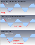
my preliminary assumption is that the positive peaks in the waveform graphs represent the outwards directed accelerations, the negative ones show the acceleration towards the inside. I'll have to check this with the higher speed slow motion footage, once I do that.

my preliminary assumption is that the positive peaks in the waveform graphs represent the outwards directed accelerations, the negative ones show the acceleration towards the inside. I'll have to check this with the higher speed slow motion footage, once I do that.
Super interesting to see the different parts of the wave cycle affected depending on which end the port is flanged!
Also somewhat counter-intuitive that the interior end flange has more effect at medium levels where as the exterior flange is more important for high levels. Why would this be? Is that displayed in the measured spectrum or just subjectively?
Anyway super intersting to visualise the effect of the flange on both the waveform and the air flow. Thank you 😊 I wish I could interpret the video of the particles better, I feel like you probably get more from it having seen many more cases / instances doing these experiments. I feel like what is happening rushes by in an instant.
Yes, that is a result of too low "sampling rate". I am confident this will change with a higher fps camera!I feel like what is happening rushes by in an instant.
But before renting it I want to build some transparent test ports to better look into them!
Yes, it can be seen in the spectrum, but it still is a quite subjective "feeling" to what noises are more nasty. for me the strong modulated high pitched hiss is most annoying. That is probably excited by air passing at high velocity over a sharp edge. It is highly directive (high frequency) and thus more audible from the exterior end of the port.Why would this be? Is that displayed in the measured spectrum or just subjectively?
Anyhow, these experiments are only relevant to understand the air flow behaviour. Any decent use for music reproduction requires absolute absence of flow noise.
That is also a "flaw" (or a limit) of my particle videos: once the turbulences are visible they are already far above audible tolerance level.
slow motion port air movement video 3: progressive geometry (elliptic wall) port
here comes the next slow motion video, with the "progressive geometry port".
I used the exising port of chamber 1 and attached it to the lower tuned chamber 2.
the tuning only changes very slightly (it's 1-2 Hz lower):
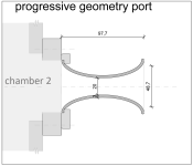
as I experienced earlier this port behaves quite well, but only up to a certain level and more importantly only down to a certain frequency.
this effect follows the strouhal-number explanation of roozen, but it is much more pronounced.
once the frequency gets really low (and thus the particle displacement distance gets big) the H3 distorsion, compression and the low frequency noise raises very rapidly. I suspect besides a relationship between displacement distance and exit radius there is another relationship between port length and displacement distance. I will investigate further!
for this rather small port and also the one in my next video (small straight tube) I used input levels from 0,125 V to 4 V rms, including 2,83 V rms.
above 4 V the particle movements are so quick that it does not make much sense to show them on 120 fps videos.
also, there is very low modulated chuffing noise, thus the slowed down audio is not very revealing, therefore it's not included here.
by the way: the strouhal numbers refer to the port exit radius.
at the end of each input voltage section there is the correlating spectrum graph.
here is the respective 1 - 4 V chuffing graph:
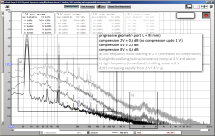
I suspect the low frequency noise is related to a circular turbulence inside the exit flange which can be seen in the video at higher levels.
also note that this port geometry seems to be quite tolerant regarding longitudinal resonance mode. there is only a very slight low peak at levels that are not usable for music reproduction anyway.
Last edited:
I wonder if you could interest Smarter Everyday or Slow Mo Guys to take up this challenge? You've done enough work to show it would be interesting. We could even write a group letter with multiple people on this forum showing interest.
The flour particles leave a streak of motion in the higher output examples and that makes it possible to see the path they are taking (such as circular). What does it look like if you simply take a single photo with an exposure length equal to half a cycle? Can we see the turbulent patterns traced out? It would be hard to time the frame just right of course but dumb luck might work out if attempted a few hundred frames.
I like the details you added in the FFT. Makes it easier to follow.
- Home
- Loudspeakers
- Multi-Way
- Investigating port resonance absorbers and port geometries
