I am coming to the same conclusion. However, by choosing the right port geometry we can get quite acceptable compromises. The relevance of the port should not be underestimated (as i did myself)!at best a medium to poor compromise to reach lower frequency output.
Have fun!going to the beach.
Couple thoughts that might help you move forward...
Your curved port was rectangular while the other two were round, so you haven't really isolated your variables. It is interesting that the port resonance was slightly lower, but in my testing where the ports were all round, the curved - let's call it Roozen port since he defined it - had a port resonance as bad as the others. Buy a 3D printer!
My resonator chamber isn't 1/4wl deep and it still works (see my post earlier in this thread), so don't be discouraged by the longer resonator you used apparently combining with the port to create a new lower resonance. I don't think the resonator needs to be that long.
I agree ports have their compromises, but keep this mind: they are very popular for a reason. For every person that notices midrange issues caused by the port resonance, there are a 1000 people that would find real issue with the bass if it were sealed.
Not up to speed on this subject so I hope it's relevant here. Searching for answers to some port related questions I ran across this post last night. The workaround looked like a simple and good idea, and he says it works. (No, not the sock ! The extension with centre holes.)
I already have access to a 3d printer and printing a round port is the planned next step!Buy a 3D printer!
here is another possible port construction technique:
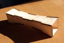
laser cut 4 mm plywood, square cross section, rounded walls.
I use a small helmholtz resonator as absorber. in this case it is 3 x 5 x 5 cm and has a small 2 cm "port", about 2,6 cm long.I don't think the resonator needs to be that long.
the resulting resonance frequency can easily be verified by blowing into the hole/the port.
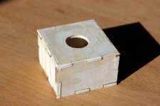
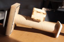
it could be interesting to see whether a long "pipe" has the same effect as the small box - even if I have realized that the semantic distinction between pipe resonator and helmholtz resonator is not that sharp in the physical sense.
No, not the sock ! The extension with centre holes.
😆
thanks for the link! very interesting ...
Last edited:
I fully agree!For every person that notices midrange issues caused by the port resonance, there are a 1000 people that would find real issue with the bass if it were sealed.
bass reflex is a very useful solution to push the physical limits of woofer excursion.
either for small drivers in home hifi or for PA.
personally I will try to stick to bigger drivers in sealed enclosures (and eventual equalization) whenever possible.
Just use high pass filter with ported speaker, otherwise the excursion is easily more than with sealed!
But how many amplifiers have a rumble filter, or operator putting it on? seeing cone move a lot means there is lots of bass, right!😀
Yeah, commercial products for consumer is different stuff than what one can fabricate for them selves, be it ported or not doesn't matter as long as it is what is expected. One could put led lights and 1000W sticker, for even better bass 😀 Just having fun, I'm sure all kinds of systems can sound better or worse.
Last edited:
diagonal interior flange
instead of building a big flange/flare at the interior end of the port - what about just cutting it diagonally?
that should increase the opening surface and eventually lower the resonance peak, because the port has not one exact length anymore ....
I first tried the following interior ends:

the result was disappointing for the diagonal port: due to the longer and even sharper edge of the port the chuffing increased significantly.
as to be expected the rounded flange was quite an improvement compared to the simple cut off cardboard tube; however the improvements (mainly regarding chuffing noise) were not as obvious as for a flange at the exterior end.
I then added a small flange to the diagonal end (had to cut off the longest end - otherwise it woud not fit!):

while there was still more chuffing noise (and chuffing longitudinal resonance peak) than with the simple flange, the diagonal flanged end both lowered H3 distorsion and increased the bass output by about 0,5 dB.
I suppose this is simply due to the increased opening surface.
I would generally not recommend this because adding a diagonal flange is rather difficult but it might be a solution to maximize output in case of simple tube ports.
by the way: the effective port length, both for longitudinal resonance and for the helmholtz tuning is just slightly longer than the shortest part of the diagonal port. I will provide effective port length/surface factors for the different ports in the next posts!
Last edited:
for completeness, here is how i measure responses and spectrum:
response: microphone in front of port, 5 cm distance. low level, about 500 mV
spectrum and distorsion: microphone on the side of the port, 10 cm distance to avoid direct turbulence at the microphone.
View attachment 1206016
the microphone is connected to an old (but good) focusrite saffire LE firewire soundcard.
i measure responses with REW (and initially with speaker workshop), spectrum and distorsion with REW.
i found perfect settings for the spectrum analyzer in @xrk971 's distorsion measurement thread. thanks!
Hello,
Looking at your photo and scratching my head.
I have started a project measuring "bass" drivers installed in enclosures. I have not got to Bass Reflex yet. A couple of musings. A BR speaker is not just a port.
Much of what you measure with with the microphone outside the port is not due to the port at all. Internal enclosure resonance is just one variable that comes to mind, panel resonance is another. Installing a port is like opening a window to let the internal reflections out. Yes the port may make sound of its' own like a whistle on a steam ship.
I have been drilling a 9/32 inch hole and placing a 1/4 inch GRAS microphone through the hole and into the box to measure what is going on inside the enclosure.
You may find that much of what you are measuring at the "outside" of the port was inside prior to the port being installed.
Thanks DT
Hi @DualTriode
did you read through the entire thread?
The main interest for me (initially) were explicitly port resonances. See thread title.
Also have a look at the internal resonance post (#19) and my attempts to reduce them (#22).
Did you also notice that I intentionally built a bandpass box, in order to concentrate on port output?
Did I mention the box being a bad example for a useful box but a good subject to investigate resonances (I did)?
Anyway, I fully agree that the port can only transfer and eventually amplify sound from the box interior. Except maybe for chuffing noise!
(Edit: how was the beach?)
Last edited:
Just to add to the collection. This fellow did his by stacking plywood rings. The geometry flares from the centre out to each end for what he calls a laminar vent.
A few years ago I saw a port done with the inside surface textured like a golf ball, presumably for the same kind of thinking though don't remember if they reported success or not.
A few years ago I saw a port done with the inside surface textured like a golf ball, presumably for the same kind of thinking though don't remember if they reported success or not.
As I am just reading again through your post ..The entire TL walls are lined with damping material and there is stuffing on the closed end, plus there are sharp corners that act to filter out these higher frequency peaks.
An interesting feature of TLs I just realized is the "longitudinal port resonance" coincides with the "port tuning".
stuffing the TL reduces resonances but also the bass output (not ideal for bandpass with only port output).
It might be interesting by the way to build a bandpass TL speaker!
Wow!! Beautiful!!what he calls a laminar vent.
Thanks for the link!
Other idea for port resonance damping is port full of drinking straws, what all have little (or more) different length. Generally handful of 3-7 mm diameter straws also damps very well ported box resonance because air friction against straw walls and handful of straws have very large wall surface.
I had experimented some times ago.
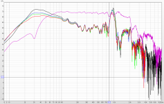
On image are port and driver in box nearfield measurements of ported speaker what had port filled with straws, red line 3 mm, green 5 mm and blue 8 mm diameter, black is original port without straws. But this measurement tells nothing about port own personal resonance.
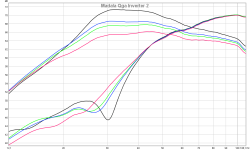
Last edited:
I always advocate using the largest port diameter or overall surface area possible, cabinet volume and tuning allowing. Sometimes fine metal screen helps smooth out thr air flow in the port to the point it doesn't become non linear flow in one direction (pumping). I've found its better to aim for a larger opening surface area than a shorter port when given the choice.
Most.port size recommendations given by sellers of kits and the like are too small. Passive radiators can sound much cleaner if sized and tuned properly for all parameters. The limiting issue is almost always excursion limits vs max diameter of the PR. The internal suspension losses can really skew the performance and low level resolution of the bass.
I absolutely despise port noise. It complelty ruins the low end integrity and natural sound of the bass.
Last edited:
Last edited:
From the general books and literature of acoustics, that is never gonna work well.Other idea for port resonance damping is port full of drinking straws,
As shown in your own measurements above.
The resonance of a pipe/tube depends on its length.
A smaller diameter would always cause a stronger boundary layer effect.
Resulting in an higher overall flow resistance.
One interesting alternative would be maybe using a t-joint structure.
Where one smaller tube ends up in the middle splitting of into two tubes (that go outside of the cabinet).
In that case you end up in a null of the standing wave inside a tube with two open ends.
If all goes well, you should be only able to measure the second harmonic.
Plus the first harmonic of the first (smaller) tube.
Here a VERY quick and dirty sketch
(source: http://labman.phys.utk.edu/phys221core/modules/m12/Standing sound waves.html )
edit: the other way around (from a double to single) would probably do the same thing.
There are some losses (plus turbulence) with the hard 90 degree angle.
Last edited:
I know stronger boundary layer effect will cause fall of Q. My idea is to have lot of pipes and all with different length, what cause dispersion of tube resonances.
Here is another idea, see my uber mega 2000 paint skills (to lazy to do it on a better way atm 😀 😀 )

So in this case what could work, is to form a tube with a one closed end (on top), and combine this with an open tube.
There is a special case when you tune the tube 1st orde resonance of the BR port equal to the 3rd order from the closed port.
Or I guess, tune the closed upper port, to the 1st resonance of the BR port rather!!
Tubes with one closed end only have odd order harmonics. (two open ends like a BR port only have even order)
In theory I think this should cancel each other out perfectly.
The closed parts of the system does have a lower resonance at f=344/(4L), but since that is below the open ports 1st order, this will never be a problem.
In addition you could add some damping material on the left side of the unused tube to dampen the higher order harmonics somewhat. I doubt if that will be an issue.
Since the end-port corrections could be a bit different, this might need some tweaking and tuning to get it right.
But I think it's quite easy to build with some off-the-shelf PVC T-joint, some regular tubing and and PVC end-stop.
- Home
- Loudspeakers
- Multi-Way
- Investigating port resonance absorbers and port geometries
