I should have mentioned the main point that was left out:here are the corresponding strouhal numbers for the flange radiusses:
small port at 2 V (start of low frequency turbulent noise) St = 0,36
small port at 4 V (turbulent noise and start of port mode chuffing) St = 0,18
big port at 4 V (start of low frequency turbulent noise, slightly less than small port at 2 V in relation to output but incuding a tiny mode chuffing peak) St = 0,42
big port at 8 V (turbulent noise and mode chuffing) St = 0,21
for both ports they start behaving badly with strouhal numbers at 0,36 or 0,42 which of course means: for strouhal number around 1 they still behave well!
how to calculate the strouhal number using max port air velocity data:
- set up a simulation of the vented box with the maximum useful input voltage to be expected (or the desired max. undistorted output). I use hornresp, using a sensible rule of thumb port flange dimension to begin with.
- look up the maximum simuated air speed for the port (usually at the helmholtz tuning frequency)
- use the formula corrected by David McBean in post #391 to calculate the max port air peak-to-peak displacement (not driver displacement!) at tuning frequency f:
displacement p-p [m] = max. airspeed [m/s] / (Pi * f)
- divide the port flange radius (use a sensible dimension and not an overly optimistic outer roundover edge radius) by the max. p-p displacement:
Strouhal number = port radius / p-p displacement
- if the strouhal number is (far) below 1 increase the port radius and recalculate the p-p port air displacement and strouhal number or reduce desired max. output. alternatively use a more straight tube port and accept noise and increased compression at all levels.
the port output frequency is strongly (more than inverse proportionally) correlated to the max. air displacement. thus lower tuning frequencies need much bigger ports!
the port (or here: port flange) radius or diameter has a more or less inverse cubic influence on the strouhal number: port air speed and displacement relates to the reciprocal square of port radius/diameter. furthermore the strouhal number is proportionally related to port radius,
thus increasing the port radius increases the strouhal number quite drastically.
it may be enough to increase the port (flage) diameter by just a bit to get the desired result.
reminder, also for myself:
strouhal number should always be higher than 1
Last edited:
the last months were quite silent here.
but from silence come new ideas!
I dug deeper into the straight and flared port geometries, trying to find out how to minimize some bad properties of flared ports.
as the roozen paper states and as I also realized, the wide flared ports have a quite sudden "collapsing" character at high air displacements.
I mainly was interested in the suspicious sudden compression (or output loss) effect of wide flared ports and had some ideas.
I made a water based simulation setup for studying and visualizing the air movement inside straight and flared ports.
a geared motor slowly rocks a water filled shallow bowl including a port shaped guide for the water and small plastic chips floating for visualisation.
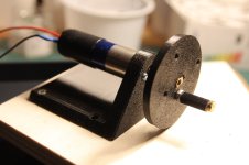
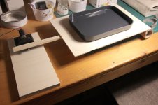
below is a video, showing the effect of flow direction separation of a straigt (flanged) and a flared port.
for a correct operation of a helmholtz port the complete port air weight must be accelerated and decelerated.
if the flow outwards and inwards are separated the effectively ac/decelerated weight of the air in the port is reduced and the system tuning frequency will raise. consequently the low frequency output (at intended tuning) will be reduced quite drastically. this is the main reason for the port "compression" effect.
while some flow direction separation (and consequent turbulent flow) can be seen for both ports, the straight port keeps working as intended, because the separation ("port blowing") happens just outside the port.
with the flared port however this flow direction separation (+turbulence) happens inside the port.
the separated airflow weight is "lost" for the helmholtz resonator and the tuning frequency raises. this is the reason for the high compression factors of flared ports at high diplacement.
so the goal is to keep all the air in the port in a mostly coherent movement.
1) classic solution: straight port with its disadvantage of compression and turbulent flow starting at low levels and tendency for very long ports to allow acceptable air speeds and displacements. long ports produce more pronounced and lower frequency resonance peaks.
2) "optimized" solution: (generously) flared port and making it big enough to avoid flow separation, again accepting long ports. exceeding the max output limit will generate quite nasty air noises and low frequency output is lost.
3) somehow keeping the air flow controlled for the optimized port ...
... some ideas will follow in this tread shortly!
but from silence come new ideas!
I dug deeper into the straight and flared port geometries, trying to find out how to minimize some bad properties of flared ports.
as the roozen paper states and as I also realized, the wide flared ports have a quite sudden "collapsing" character at high air displacements.
I mainly was interested in the suspicious sudden compression (or output loss) effect of wide flared ports and had some ideas.
I made a water based simulation setup for studying and visualizing the air movement inside straight and flared ports.
a geared motor slowly rocks a water filled shallow bowl including a port shaped guide for the water and small plastic chips floating for visualisation.


below is a video, showing the effect of flow direction separation of a straigt (flanged) and a flared port.
for a correct operation of a helmholtz port the complete port air weight must be accelerated and decelerated.
if the flow outwards and inwards are separated the effectively ac/decelerated weight of the air in the port is reduced and the system tuning frequency will raise. consequently the low frequency output (at intended tuning) will be reduced quite drastically. this is the main reason for the port "compression" effect.
while some flow direction separation (and consequent turbulent flow) can be seen for both ports, the straight port keeps working as intended, because the separation ("port blowing") happens just outside the port.
with the flared port however this flow direction separation (+turbulence) happens inside the port.
the separated airflow weight is "lost" for the helmholtz resonator and the tuning frequency raises. this is the reason for the high compression factors of flared ports at high diplacement.
so the goal is to keep all the air in the port in a mostly coherent movement.
1) classic solution: straight port with its disadvantage of compression and turbulent flow starting at low levels and tendency for very long ports to allow acceptable air speeds and displacements. long ports produce more pronounced and lower frequency resonance peaks.
2) "optimized" solution: (generously) flared port and making it big enough to avoid flow separation, again accepting long ports. exceeding the max output limit will generate quite nasty air noises and low frequency output is lost.
3) somehow keeping the air flow controlled for the optimized port ...
... some ideas will follow in this tread shortly!
Now that is something unexpected! Great study. Threads like this are the highlights of DIYaudio.
Maybe you can place colored plastic chips - say, red - inside the "loudspeaker" - and green outside, to better visualize mass exchange between volumes? Not that interesting for home hi-fi, but really useful for pro sound, where a lot of heat needs to be vented outside the cabinet. JBL paper stated that, experimentally, high turbulence straight ports are the best in that regard. Who knows, there might be some compromise designs that strike the balance between chuffing/distortion, suddend air stall at high flow velocity and heat exchange.
Maybe you can place colored plastic chips - say, red - inside the "loudspeaker" - and green outside, to better visualize mass exchange between volumes? Not that interesting for home hi-fi, but really useful for pro sound, where a lot of heat needs to be vented outside the cabinet. JBL paper stated that, experimentally, high turbulence straight ports are the best in that regard. Who knows, there might be some compromise designs that strike the balance between chuffing/distortion, suddend air stall at high flow velocity and heat exchange.
3) somehow keeping the air flow controlled for the optimized port ...
Although one sees ports with golf-ball like dimples it is likely more of a marketing feature rather than an engineering one because the Reynolds Number is likely too small for them to be effective in raising the wall shear stress to enable the boundary layer to go further against an adverse pressure gradient. You will likely need to look at larger vortex generating devices in order to be effective. Such devices are reasonably common on aerodynamic surfaces. Wind turbine vortex generators might be a good place to look for types and inspiration.
There was certianly one study where they glued glass beads on the port wall and noise increased.
thanks @VoxCelestial, @maiky76, @Tenson, and @andy19191 for the kind, useful and encouraging words!
the paper you linked, maiky76 is very interesting (and the included videos!).
I recently saw a similar shape port in a youtube video:
flared ports are made to reduce the air speed (and air displacement) at the exits, which is good, of course.
however by just expanding the port diameter there are two coinciding negative effects, as far as I see it:
both effects amplify eachother and lead to turbulent flow and loss of accelerated port mass (tuning frequency increase and low frequency output loss).
the paper you linked, maiky76 is very interesting (and the included videos!).
I recently saw a similar shape port in a youtube video:
flared ports are made to reduce the air speed (and air displacement) at the exits, which is good, of course.
however by just expanding the port diameter there are two coinciding negative effects, as far as I see it:
- flow reversal near the port walls induced by wall curvature
- flow separation due to high speed air inertia effect ("jet" forming)
both effects amplify eachother and lead to turbulent flow and loss of accelerated port mass (tuning frequency increase and low frequency output loss).
An increase in noise when the boundary layers have let go seems likely given vortex generators increase vorticity. A working vortex system offers the prospect of extending the "quiet" operation to higher velocities before the flow switches to the more intense one of the air not following the flaring wall. It is seeking to extend what flaring does.There was certianly one study where they glued glass beads on the port wall and noise increased.
There was certianly one study where they glued glass beads on the port wall and noise increased.
That was Harman (Devantier or Welti?). IIRC their explanation was that such a feature may help when you are above the Reynold's number and in fully turbulent airflow. That is not the state most ports are operating in, even when when they begin to chuff and compress, which they suggest is a mixed laminar and turbulent state. The implication is that solutions for fully turbulent conditions are not where we should focus.
An increase in noise when the boundary layers have let go seems likely given vortex generators increase vorticity. A working vortex system offers the prospect of extending the "quiet" operation to higher velocities before the flow switches to the more intense one of the air not following the flaring wall. It is seeking to extend what flaring does.
I've only ever seen vortex generators used where airflow is in one direction, not reversing, generally at a 15 degree angle to airflow. Perhaps it would be possible to design a vortex generator that works in both directions, though it is no where near my wheelhouse.
The reversed flow is accelerating and will stay attached with devices in the way. There will be an increase in losses/damping but for a speaker port this is generally not much of an issue if in moderation.
The most effective is likely to be some complex multi-channel phase plug like device which might be fun designing. Not sure it would be worthwhile in an engineering sense although for some small speakers maybe. Perhaps it may work as a distinguishing marketing feature for an audiophile speaker in the manner of KEF's metamaterial absorption technology.
The most effective is likely to be some complex multi-channel phase plug like device which might be fun designing. Not sure it would be worthwhile in an engineering sense although for some small speakers maybe. Perhaps it may work as a distinguishing marketing feature for an audiophile speaker in the manner of KEF's metamaterial absorption technology.
I guess for the sake of science and documentation it makes sense to also post some very bad ideas I had.
one was the following.
I wanted to make an air guide to avoid the turbulent (flow direction separating) air flow at the exit of the port.
this was my first try:
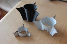
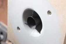
the results were bad, very bad. the small tube turned into a whistle making funny noises at low volumes.
I tried to smooth the surface, shorten the guiding ring, but no success.
It's not good to have any sharp edges in the port!
so no success by itself, but still some useful findings!
one was the following.
I wanted to make an air guide to avoid the turbulent (flow direction separating) air flow at the exit of the port.
this was my first try:


the results were bad, very bad. the small tube turned into a whistle making funny noises at low volumes.
I tried to smooth the surface, shorten the guiding ring, but no success.
It's not good to have any sharp edges in the port!
so no success by itself, but still some useful findings!
An interesting patent review of a resonance reducing port concept:
https://audioxpress.com/article/patent-review-bass-reflex-speaker-cabinet-having-a-recessed-port
The article also includes a short overview of other resonance reduction concepts at the end!
https://audioxpress.com/article/patent-review-bass-reflex-speaker-cabinet-having-a-recessed-port
The article also includes a short overview of other resonance reduction concepts at the end!
- Home
- Loudspeakers
- Multi-Way
- Investigating port resonance absorbers and port geometries
