I doubt you will have issues with dropouts. 🙂 Give it a go first and let me know how it works out. 😎
Cheers!
Russ
Cheers!
Russ

Attachments

Last edited:
Please take this to the support forum. It is not directly related to the Teleporter.
EDIT: Also, it would be helpful to see the portion of the schematic with the DAC chip.
EDIT: Also, it would be helpful to see the portion of the schematic with the DAC chip.
Last edited:
Some questions about the TP Teleporter transceiver:
1) Does it buffer or amplify the I2S signal in any way?
2) If it doesn't then what does it do?
3) How close does it have to be, in inches or mm, to the source I2S pins on the DAC?
Carlos
1) Does it buffer or amplify the I2S signal in any way?
2) If it doesn't then what does it do?
3) How close does it have to be, in inches or mm, to the source I2S pins on the DAC?
Carlos
Some questions about the TP Teleporter transceiver:
1) Does it buffer or amplify the I2S signal in any way?
2) If it doesn't then what does it do?
3) How close does it have to be, in inches or mm, to the source I2S pins on the DAC?
Carlos
1&2: It does buffer. See the DS91M040 datasheet for more information.
3. Generally speaking, it is best to keep I2S signals as short as possible, so, the closer the better.
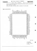
Pending the receipt of my Teleporter (should arrive this week) I've been trying to work out the I2S output connections on my Teralink USB - SP/DIF convertor.
The latter uses a CAT5 socket to output the I2S but I've soldered some output wires directly to its output pins for the sake of neatness.
I confess to being a bit confused with the connections, which are labelled GND (no problem), MCLK (which i guess is master clock and isn't needed), LRCK (to D1), Data (D2) and SCLK, which is ? My guess is DCK but I'd appreciate some help please.
PCM
0 bit clock
1 word clock
2 data
3 optional master clock (typically not used)
DSD
0 bit clock
1 data left
2 data right
3 (unused for asynchronus stereo - but could possibly be master clock)
0 bit clock
1 word clock
2 data
3 optional master clock (typically not used)
DSD
0 bit clock
1 data left
2 data right
3 (unused for asynchronus stereo - but could possibly be master clock)
Last edited:
Hi Merlin, thanks, I did read this but couldn't quite understand -
I'm connecting I2S, which is the same as DSD? It seems I need to connect up from my Teralink I2S to the Teleporter as follows :-
Teleporter
0 = SLCK (on Teralink)
1 = LRCK " "
2 = Data " "
I therefore ignore the ground connection and the MCLK connections on the Teralink? All help gratefully received!
It doesn't matter which signal you tie to which teleporter channel, as long as you use the same arraignment on both ends. The order you list will work fine.
Teleporters
HI,
I have the teleporters up and running.
PC->Teradac Terelink module via I2s ->Teleporter->6'cat5->Teleporter->I2s input on sidecar.
Set the transmit teleporter to open/off and the receiver teleporter to closed/on.
Tony- I have the module, you may have the cased teradac. But I use this for connections and it works. LRCK->D1/LRCK, Data->D2/Data, SCLK->BCK, no ground connection.
I made a little lm7802 ps @ 4.8v for the teradac/pc end and used the lcdps @5.0v in the dac case to power the teleporters.
After reading some threads I set the SW1 #5 and #8 on, SW2 #5 and #8 on, all other switches off. I now can use the teradac usb-i2s converter without the constant dropouts I had before. In the past the teradac was unusable via i2s. I could use it with the spdif out but the i2s sounds better. The dac will still drop the signal occasionally but is usable. SQ is very close the the shigaclone transport when using the i2s connection on the teradac. 🙂🙂🙂
Many thanks Bikerboy, that's just the information I was after!
Regarding the SW switches, I'm using a Dual-Mono Buffalo II so I'm not quite sure how this translates, maybe Brian will have the answer. It's reassuring to know the Teralink's I2S output works though.
My Teradac started out as a cased one but I've modified it quite a bit -
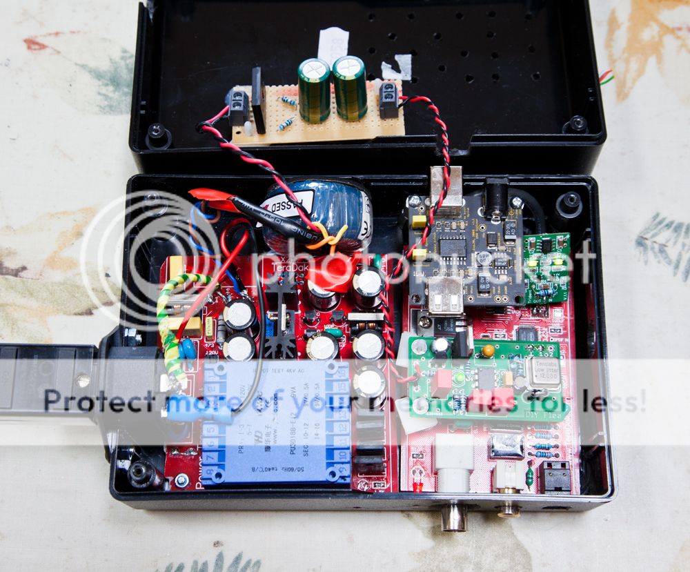
(Sorry we're drifting a bit off-topic here...)
Regarding the SW switches, I'm using a Dual-Mono Buffalo II so I'm not quite sure how this translates, maybe Brian will have the answer. It's reassuring to know the Teralink's I2S output works though.
My Teradac started out as a cased one but I've modified it quite a bit -
(Sorry we're drifting a bit off-topic here...)
- Home
- More Vendors...
- Twisted Pear
- Introducing the bit "Teleporter"