Fantastic work Michael you are a true artist of your profession...
To pull some heat out of the job perhaps you could use something like a peltier?
http://en.wikipedia.org/wiki/Thermoelectric_effect
To pull some heat out of the job perhaps you could use something like a peltier?
http://en.wikipedia.org/wiki/Thermoelectric_effect
Long time since the last post….but I´m excavating this thread because I actually working on a modification of the system.
Status quo:
each side:
BMS4590 in my elliptical horns – 420Hz-20kHz
2xEminence Omega Pro 12 in vented enclosures - 70-420Hz
1xB&C 15PS100 in 28Hz tapped horns - 28-70Hz
DSP controlled
Since I built those speakers, I always dreamt of making some matching upperbass horns, too. The vented 12” are okay, have good attack, but I always looked for a way to improve the transition to those really fast mid/high horns and improve the bass quality as well.
I´ve made several rough calculations and sketches in the last 6 years, but I never refined those, neither concerning the technical aspect nor concerning their appearance.
My right speaker is very close to / extending into a passageway and my drafts always struggled to not further narrowing that passageway, which caused some controversy with my wife.
I wasn´t keen to fold or roll those horns, because with a crossover @420Hz I wanted them to deliver smooth HF output till appr. 800Hz.
Last weeks I started working on that horn-concept again.
Finally I came up with a 2x12" (Eminence Omega Pro 12) design that satisfied me.
I chose to go for 2 drivers, because with the double throat area the horn can be 20cm shorter with same f cutoff / without loosing hornloading at the bottomend. Lateron measurements will have to show, if 2 driver will cause problems at the upper crossover region. The throatchamber and throat entries are separated and both paths meet some way up the horn. I hope this will be sufficient to avoid any HF problems.
The horn itself is about 1m long (incl. a small throatchamber of 4cm), the backchamber will be a short as possible, appr. 16-17cm (10l for each driver).
They will be about 120cm long (47 ') over all, mouth will be 75cm high (30') and 115cm wide (45')
and should deliver a smooth response from 80Hz till 420Hz with smooth rolloff on both sides.
Hardest thing has been getting those numbers from the simulation into shape:
I wanted the horn to be elliptical. The reasons are:
Minimizing reflections (compared to square or round horns)
Maximizing horn loading from the ground plane (compared to round horns)
Matching the look of the mid/high horns
Last but not least it suits the two driver approach fine.
If you want all wavepathes to be identically long from throat to mouth, the mouth of an elliptical horn will not be a plane as we all know.
To be honest, this will most likely make absolutely no difference for a 80Hz-400Hz horn.
But bending the right and left "sides" back will give me a little more clearance for the passageway. Besides that I hope it will look less clumsy and a little more "organic".
The plan is:
-make a CAD Model (done)
-cut it in 40mm slices and transfer those shapes to 40mm thick polythyrene (done)
-glue the slices together and smooth everything roughly (mostly done)
-get the approval from my wife for that 1:1 model (done, albeit there has been some nagging from her "does it have to be that big ?")
- add an inner and an outer shell of appr. 20mm concrete/plaster reinforced with short fibres and fiberglass mesh.
Because of the shell shape, the material and the sandwich structure, this should hopefully result in a really rigid horn.
- build the throat adapter and the backchamber from wood and metall
- repeat all steps for horn nr. 2
- paint them white
- fire those beasts up
I´m really curious how this turns out. Will the horns be rigid enough, how will they measure and most important what will they sound ?
Status quo:
An externally hosted image should be here but it was not working when we last tested it.
each side:
BMS4590 in my elliptical horns – 420Hz-20kHz
2xEminence Omega Pro 12 in vented enclosures - 70-420Hz
1xB&C 15PS100 in 28Hz tapped horns - 28-70Hz
DSP controlled
Since I built those speakers, I always dreamt of making some matching upperbass horns, too. The vented 12” are okay, have good attack, but I always looked for a way to improve the transition to those really fast mid/high horns and improve the bass quality as well.
I´ve made several rough calculations and sketches in the last 6 years, but I never refined those, neither concerning the technical aspect nor concerning their appearance.
My right speaker is very close to / extending into a passageway and my drafts always struggled to not further narrowing that passageway, which caused some controversy with my wife.
I wasn´t keen to fold or roll those horns, because with a crossover @420Hz I wanted them to deliver smooth HF output till appr. 800Hz.
Last weeks I started working on that horn-concept again.
Finally I came up with a 2x12" (Eminence Omega Pro 12) design that satisfied me.
An externally hosted image should be here but it was not working when we last tested it.
An externally hosted image should be here but it was not working when we last tested it.
I chose to go for 2 drivers, because with the double throat area the horn can be 20cm shorter with same f cutoff / without loosing hornloading at the bottomend. Lateron measurements will have to show, if 2 driver will cause problems at the upper crossover region. The throatchamber and throat entries are separated and both paths meet some way up the horn. I hope this will be sufficient to avoid any HF problems.
The horn itself is about 1m long (incl. a small throatchamber of 4cm), the backchamber will be a short as possible, appr. 16-17cm (10l for each driver).
They will be about 120cm long (47 ') over all, mouth will be 75cm high (30') and 115cm wide (45')
and should deliver a smooth response from 80Hz till 420Hz with smooth rolloff on both sides.
Hardest thing has been getting those numbers from the simulation into shape:
I wanted the horn to be elliptical. The reasons are:
Minimizing reflections (compared to square or round horns)
Maximizing horn loading from the ground plane (compared to round horns)
Matching the look of the mid/high horns
Last but not least it suits the two driver approach fine.
If you want all wavepathes to be identically long from throat to mouth, the mouth of an elliptical horn will not be a plane as we all know.
To be honest, this will most likely make absolutely no difference for a 80Hz-400Hz horn.
But bending the right and left "sides" back will give me a little more clearance for the passageway. Besides that I hope it will look less clumsy and a little more "organic".
The plan is:
-make a CAD Model (done)
-cut it in 40mm slices and transfer those shapes to 40mm thick polythyrene (done)
-glue the slices together and smooth everything roughly (mostly done)
-get the approval from my wife for that 1:1 model (done, albeit there has been some nagging from her "does it have to be that big ?")
- add an inner and an outer shell of appr. 20mm concrete/plaster reinforced with short fibres and fiberglass mesh.
Because of the shell shape, the material and the sandwich structure, this should hopefully result in a really rigid horn.
- build the throat adapter and the backchamber from wood and metall
- repeat all steps for horn nr. 2
- paint them white
- fire those beasts up
I´m really curious how this turns out. Will the horns be rigid enough, how will they measure and most important what will they sound ?
An externally hosted image should be here but it was not working when we last tested it.
An externally hosted image should be here but it was not working when we last tested it.
An externally hosted image should be here but it was not working when we last tested it.
An externally hosted image should be here but it was not working when we last tested it.
Michael, looking good! Very nice fabrication skills. 🙂
Your shop practices could be far, far better tho.
A dust mask is not a proper respirator when spraying finishes of any sort.
Also, you need to protect yourself from dust better. Having fine dust from mdf and adhesive is not what you want caked in your eyes and in the air you breath. None of this is worth damaging your health over. 😉
Those big horns are interesting to look at. They have an organic artsy quality to them. Great job!
A dust mask is not a proper respirator when spraying finishes of any sort.
Is there an old picture somewhere ?
You are of course absolutely right. It cannot be repeated too often.
Don´t mess with you health.
I wasn´t as careful as I should have been when I was a student about 10 years ago.
Usually (and always in the last years) I use breathing protection with the appropriate filter cartridges.

I´m very careful now, always wearing ear protection, goggles and respirator with different filters when needed.
(painting, TIG welding, brazing, grinding etc.)
Of course I wore a respirator, google and ear plugs when I sanded the styrofoam core of this horn.
Last edited:
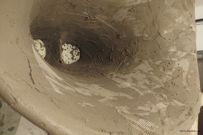
I made the first 4cm of the horn, which are made out of MDF. I added M6 thread inserts to bolt the backchamber to the horn lateron.
The MDF is glued to the styrodur with PU-glue. I added additional thread-rods to strengthen the connection to the Styrodur and the concrete-shell.
I mixed Styrodur chops with mortar and filled the steps and buckels of the outside with this putty.
Then the first 30kg batch of mortar and fibre-cloth was applied to the outside.
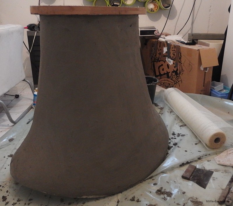
While this layer dries, I´ll start drawing the contours for the second horn and start cutting those from the styrodur.
The MDF is glued to the styrodur with PU-glue. I added additional thread-rods to strengthen the connection to the Styrodur and the concrete-shell.
I mixed Styrodur chops with mortar and filled the steps and buckels of the outside with this putty.
An externally hosted image should be here but it was not working when we last tested it.
Then the first 30kg batch of mortar and fibre-cloth was applied to the outside.
An externally hosted image should be here but it was not working when we last tested it.
An externally hosted image should be here but it was not working when we last tested it.
While this layer dries, I´ll start drawing the contours for the second horn and start cutting those from the styrodur.
Last edited:
hard working....
An externally hosted image should be here but it was not working when we last tested it.
An externally hosted image should be here but it was not working when we last tested it.
An externally hosted image should be here but it was not working when we last tested it.
An externally hosted image should be here but it was not working when we last tested it.
Thanks.

Somehow all my projects tunr out to be big, heavy and coarse.
But I must admit I love the exhausting "sculptural" (which is a big exaggeration and euphemism, but I can´t find another word for that) working / shaping.
A fellow over at Lenco Heaven said:
"Most of us have a great 3D printer already, it's called a hand."
So true. I should use and train it more often.
I put a thick second outer layer on Nr. 1 yesterday. Now it needs to dry and harden before I turn it over and put on the next concrete layers.
So it was time to create a twin.....core Nr. 2 almost ready.
What a mess. 😱😱
An externally hosted image should be here but it was not working when we last tested it.
An externally hosted image should be here but it was not working when we last tested it.
MiWi,
Give CESSARO speaker website a look ( also in Germany ), If you haven't already. Ralpf also now uses a casting process for making his horns. Probably one of the best sounding speakers on the planet !!!! But VERY expensive. Make your horns the best you can ---and cry once !!! Best of luck.
Give CESSARO speaker website a look ( also in Germany ), If you haven't already. Ralpf also now uses a casting process for making his horns. Probably one of the best sounding speakers on the planet !!!! But VERY expensive. Make your horns the best you can ---and cry once !!! Best of luck.
I know the cessaros quite well.
They are one reason for this project.
I´m often listening to Thomas Woschniks speakers (TW Acoustic, I designed his Raven 10.5 tonearm). He owned several Cessaros over the last years.
I always wanted big midbasshorns, but since Thomas got his (custom) Omegas, I knew I had to build my horns.
I totally loved what I heard from the Gammas and Omegas.
I totally confounded the models.
(had to look at the Cessaro site)
I think Thomas actually got a Beta I with custom fl sub-horns.
Anyway....the whole concept is very good sounding.
(had to look at the Cessaro site)
I think Thomas actually got a Beta I with custom fl sub-horns.
Anyway....the whole concept is very good sounding.
Last edited:
Applied the last layers of mortar inside and outside.
Each took my nearly 4 hours incl. smoothing.
The surface is bumpy, but this is as far as I can get with concrete.
I won´t do no harm to sonic waves with wavelenght about 1 to 4 meters.
But for the look a buddy suggested smoothing everything with resin filling compound, do excessive sanding and paint it to high gloss finish.
But this will be more agony than I want to take.
My plan was and still is to just give it some thick layers of epoxy floor coating and a finishing layer of silk matt white (this will mask the bumps).
I will start working on the compressionchamber and backchamber as soon as I get the MDF from the wood retailer.
When those are finished, I will measure this first horn before continuing to work an Nr. 2.
This will give me some time to decide which way to go for the painting / finishing work.
An externally hosted image should be here but it was not working when we last tested it.
An externally hosted image should be here but it was not working when we last tested it.
An externally hosted image should be here but it was not working when we last tested it.
MiWi,
Looks very good !!! You took on a very labor intensive project. Grind down the biggest lumps, use a little automotive body filler, finish with a few layers of textured epoxy paint and call it a wrap !!! Should sound excellent !!!
Looks very good !!! You took on a very labor intensive project. Grind down the biggest lumps, use a little automotive body filler, finish with a few layers of textured epoxy paint and call it a wrap !!! Should sound excellent !!!
Thanks for the tip.
Yesterday I took a sanding block and gave some of the lumps (on the hornmouth) a wipe.
The mortar is dry but still quite loose, so the sanding worked out great.
I´ll buy some concrete primer/sealing first, by now the surface looses some sand each time I wipe it with my hands.
When the surface is sealed I´ll use some automotive filler.
Thanks for mentioning textured paint. That was what I had in mind but I struggled to find the right word/translation for it.
Sealed and primered.
Now the surface is stable enough to carry this thing around for the measurements.
I started working on the compressionchamber and backchamber assembly.
The compressionchamber is a modular design.
By now it´s volume gives me a lowpass @ 400Hz and a little more efficiency around 80-100Hz.
But I will make inserts to reduce the volume of the compression chamber and instead add 6cm of hornlength / bring the hornthroat directly in front of the driver (which will give slightly more compression ratio because of a little smaller throat)
I´ll measure and listen to both options and will.
Now the surface is stable enough to carry this thing around for the measurements.
An externally hosted image should be here but it was not working when we last tested it.
An externally hosted image should be here but it was not working when we last tested it.
An externally hosted image should be here but it was not working when we last tested it.
I started working on the compressionchamber and backchamber assembly.
The compressionchamber is a modular design.
By now it´s volume gives me a lowpass @ 400Hz and a little more efficiency around 80-100Hz.
But I will make inserts to reduce the volume of the compression chamber and instead add 6cm of hornlength / bring the hornthroat directly in front of the driver (which will give slightly more compression ratio because of a little smaller throat)
I´ll measure and listen to both options and will.
An externally hosted image should be here but it was not working when we last tested it.
An externally hosted image should be here but it was not working when we last tested it.
An externally hosted image should be here but it was not working when we last tested it.

An externally hosted image should be here but it was not working when we last tested it.
An externally hosted image should be here but it was not working when we last tested it.
An externally hosted image should be here but it was not working when we last tested it.
An externally hosted image should be here but it was not working when we last tested it.
An externally hosted image should be here but it was not working when we last tested it.
- Status
- Not open for further replies.
- Home
- Loudspeakers
- Multi-Way
- Introducing me and my speakers