A small Experiment
Hi Guys !
I tried small Experiment that with PSU without constant voltage regurater.(for amp_circuit and Power circuit , using same PSU)
Result
1.Thereis no hum noize from speaker.
2.At no inputsignal:
the PSU Voltage is +28V/-28V
and 0.2Vpp liple.
3.Max power ( 16W 8hom register load) ,
the PSU Voltages is down to +27V/-27V and
0.5Vpp liple with 0.1Vpp signal wave according
to the input signal is .
The max voltage to the polyester film capacitor is remarkably decreasing at the high frequency.
( ex:there were a case it decreases up to about 10V even by
630V(DC) in 20KHz in.
Therefore, it was felt that it was good there is a constant voltage regurater the case of use cap of 50V.( in this circuit C16,C17)
Regards
Attachments

New AMP "MK2"
HI guys!
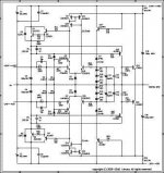
I have designed A new circuit.
For Hi power ,For Hi voltage .
The input FET of first stage was weak point of Hi voltage .
So I design with bipola Tr for trans inpedance circuit of inverted and
current feed back.
It works now ,and is on tuning .
Regards.
HI guys!
I have designed A new circuit.
For Hi power ,For Hi voltage .
The input FET of first stage was weak point of Hi voltage .
So I design with bipola Tr for trans inpedance circuit of inverted and
current feed back.
It works now ,and is on tuning .
Regards.
Attachments

Hi guys.
Tuneing repo.
It treats by the base resister for the dumping though the ringing has generated by the first stage is a tentative value.
Moreover, Q15 and 16 are similarly treated and Vbe is stabilized. (Resistance is a little large because of tentative. )
Regards
Tuneing repo.
It treats by the base resister for the dumping though the ringing has generated by the first stage is a tentative value.
Moreover, Q15 and 16 are similarly treated and Vbe is stabilized. (Resistance is a little large because of tentative. )
Regards
Attachments
Hi TurnA,
So what's the new power rating of your amp? Seems like your amp is getting more interesting. 😀
I have designed A new circuit.
So what's the new power rating of your amp? Seems like your amp is getting more interesting. 😀
Hi ! fredlock .
Thank you for your reply.
The rating is,
60W-70W (eight-ohm load) is designed with a current circuit.
If the capacitor with high voltage rating is used, a higher voltage can be driven.
Of course, though appropriate heat radiation is necessary.
Regards!
Thank you for your reply.
The rating is,
60W-70W (eight-ohm load) is designed with a current circuit.
If the capacitor with high voltage rating is used, a higher voltage can be driven.
Of course, though appropriate heat radiation is necessary.
Regards!
A New AMP etc
Hi !
I made a new Amp.
Power up max 60W and some refines.
main circuit
http://www2.plala.or.jp/puthoff/gazou_mk2/amp_WD_MS010_Mk2.GIF
constant Vol regulator
http://www2.plala.or.jp/puthoff/gazou_mk2/cvr.GIF
precharge circuit
http://www2.plala.or.jp/puthoff/gazou_mk2/rly_pow.GIF
Speaker protect
http://www2.plala.or.jp/puthoff/gazou_mk2/rly.GIF
psu
http://www2.plala.or.jp/puthoff/gazou_mk2/psu.GIF
ALL
http://www2.plala.or.jp/puthoff/photo4/zentai.JPG
Regards
Last edited:
Some refine
Hi !
I have some refine of the new Amp Power up max 60W .
main circuit
http://www2.plala.or.jp/puthoff/gazou_mk2/amp_WD_MS010_Mk2.GIF
(I have overwrite the FIG)
Q3,Q4 (C2362K/A1016K) to C2705Y/A1145Y
The register of Power MOS FET is lessed.
R13,R18 for DC servo is 10kohm/470kohm to 1Kohm/47kohm,
so Good for the OPamp that input is bi poler Tr about noise.
(this type LPF canseling music signal is able to decrease the register number)
Regard!
Last edited:
Only a idea of amp
Hi All!
I have a only chip idea of AMP circuit diagram with OP Amp.
( may be already many have known ...)
The one that a part of circuit of my recent amplifier was cut out,
and It modified views.
I think that the second one is easy to make high Voltage OP amp...
(It is current F/B type )
New explain the recent amp working
http://www2.plala.or.jp/puthoff/material/EXP_MK2_V2.pdf
Regards
Attachments
Last edited:
Thank you
Thank you The Guy,your comment and advices.
I think that the sound by increasing outputVOL useing supply rail of OPamp is nallow range sound....so ,I 'll thinking and study more more now and in the future,to similar.
P.S
I know the reason why your reply was soon deletion ,but I understand your geniality,
Very very thank you.
Regards
UPLOAD YOU TUBE the Circuit description trying
HI !
I have tried to uoload Circuit description.
YouTube - 60W MOS FET DC Power Amplifier
It was quite interesting.
Regards!
HI !
I have tried to uoload Circuit description.
YouTube - 60W MOS FET DC Power Amplifier
It was quite interesting.
Regards!
Some Simulation study
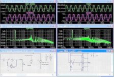
Hi I have Some Simulation study.
first about this AMP circuit
"http://www2.plala.or.jp/puthoff"
It is a result of comparing the control deflection with LT1364 and MK2 type circuit
(Parts are different in a simulation and a real machine. Because I do not have the data of the part. )
<Condition>
Feedback circuit :1k ohm / 47k ohm (GAIN 47 times)
The load resistance : 1k ohm
Input signal :1KHz sin wave - 200mV (DC offset cancellation in the input element.)
Output : 9.4V
<Results>
(1) deviation
LT1364 : 3.2 mV
MK2 : 24nV
(2) the inversion of the open-1KHz
LT1364: times 5875 (75.4dB)
MK2: double 783333333 (177.9dB)
<Data>
The study chart
Attachments
Last edited:
Second study
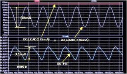
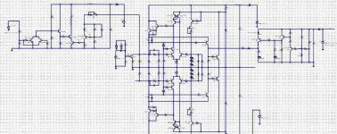
Hi second study,it's about CVR
The small signal Tr 2SC1815/A1015, output Tr 2SC4973/A1837 are the alternative .
The output voltage is approximately 34V
Output current
f = 1KHz and 100KHz
DC: 115mA to AC: ± 40mA output current superimposed state.
Output impedance
1KHz: 3.75mΩ
100KHz: 6.25mΩ
Hi second study,it's about CVR
The small signal Tr 2SC1815/A1015, output Tr 2SC4973/A1837 are the alternative .
The output voltage is approximately 34V
Output current
f = 1KHz and 100KHz
DC: 115mA to AC: ± 40mA output current superimposed state.
Output impedance
1KHz: 3.75mΩ
100KHz: 6.25mΩ
Attachments

thrd study
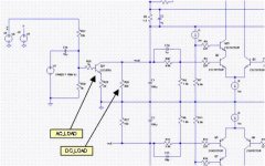
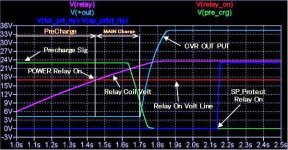
Hi third study .it's about precharge to power Relay on ,to maincharge and CVR begin to start and SP protect Relay ON.
1.Power relay circuit is delayed by CR circuit.
While this time the precharge signal is on output.
2. The power relay is ON when 17V.
Then, it gradually turns OFF pre-charge signal.
3. When the precharge signal become OFF, the constant voltage regulator begin to start.
4. When the output voltage of constant voltage regulator become high enough, Speaker protect Relay is connected.
Attachments
Sorry I have miss.(2) the inversion of the open-1KHz
LT1364: times 5875 (75.4dB)
MK2: double 783333333 (177.9dB)
It is a correction.
(2) the inversion of the open-1KHz
LT1364: 5875 times (75.4dB)
MK2: 783333333 times (177.9dB)
Regards!
- Status
- Not open for further replies.
- Home
- Amplifiers
- Solid State
- Intro a circuit of study..