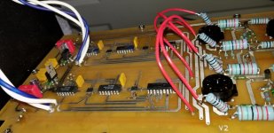
Yes, I ruled out everything beyond the digital volume circuitry by lifting the L and R output circuits and rerouting the L signal from the digital volume network, to the tube input of the R channel and visa versa. The noise followed the L digital volume network. See image, attached.Have you considered the tube sockets?
Attachments

Thanks... a bit more of a commitment than I bargained for, saying I'd help a friend😱.Congratulations. Persistence pays off.
thanks for the help - Analog & John...
V2
See image, attached.
Wow, did not notice this before. Very nicely done

Vsquared,
My diy Ref3 works fine, I was just wondering how AR did some things. Do you remember what the LT1085 powers and what the output voltage is? Do they draw the -15volts for the CCS from the same source as the voltage that feeds the regulators for the volume control chips. (from the same diodes as the negative heaters)
Thanks in advance.
Hi Johnmarkp -
Unfortunately I never found the power supply board schematic and can't recollect the details any longer, sorry.
V2
Unfortunately I never found the power supply board schematic and can't recollect the details any longer, sorry.
V2
Attachments
Last edited:
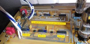
Well folks, this closes the chapter for the culprit of the background noise in the left channel... it turned out to the the Maxim MAX5437 Digital Potentiometers... They were not at all fun to replace, being surface mount devices, but we're all good now. And as for the 2400pF Polystyrene decoupling caps that was seeking, I went with the REL RELCAP-51620, 600v RTE caps from Parts Connexion and had them match all 4 for me. So we're good to go... finally.
I love the mix of technologies from across the ages - valves, DIP and smt....
Last edited:
Hello DIYers,
I am currently trying to get my Ref 3 back on its feet and it seems the above REL RELCAP-51620, 600v is no longer listed on the Parts connection website. Could anyone advise me on which would be a suitable replacement from this link?
Rel-Cap RTE Series Film Capacitors
Thanks.
I am currently trying to get my Ref 3 back on its feet and it seems the above REL RELCAP-51620, 600v is no longer listed on the Parts connection website. Could anyone advise me on which would be a suitable replacement from this link?
Rel-Cap RTE Series Film Capacitors
Thanks.
I have been replacing the Max 5437 as I've had the identical problem as Vsquared. one of the foil caps has broken in half hence the need for replacement.
The info that I have found on the originals is 0.0024 uf and the same value can be found on a US site called TEDSS but they want $200 to find and ship them which is a little excessive. It's the 0.0024 value that I can't find on other sites and I'm not sure if a higher or lower value would be appropriate. As far as the voltage goes the ones on TEDSS are 160V 2.5% tolerance but I am guessing that these are the same as origonals.
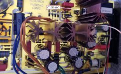
The position in the amp is running in parallel with 4 capacitors you can see them on the attachment marked as C111 and C112
The info that I have found on the originals is 0.0024 uf and the same value can be found on a US site called TEDSS but they want $200 to find and ship them which is a little excessive. It's the 0.0024 value that I can't find on other sites and I'm not sure if a higher or lower value would be appropriate. As far as the voltage goes the ones on TEDSS are 160V 2.5% tolerance but I am guessing that these are the same as origonals.
The position in the amp is running in parallel with 4 capacitors you can see them on the attachment marked as C111 and C112
Attachments
It's a bypass capacitor, and whether it must be there at all, or can be changed, is just a matter of preference.
However, any replacement must be the same or higher voltage rating, and have low inductance.
However, any replacement must be the same or higher voltage rating, and have low inductance.
Last edited:
ARC frequently use this in their amps. It's believed that a small value cap in parallel with a large one will yield better impulse response and/or improved high frequency detail, extension, etc. Any decent film cap should work well. The exact value isn't that critical. If you want to get creative you could try a small value teflon cap. Maybe one of the russian teflon caps perhaps.
Good luck, S.
Good luck, S.
With a huge thank you to the participants of this thread, my Ref 3 is back up and running. The problem with mine was exactly the same scratchy/static noise in the left channel as Vsquared experienced. I am capable of doing the work but I am no EE so the diagnosing of a fault is problematic. Replacing the MAX 5437 was quite a challenge and I ended up using a 1mm ball of bluetak behind the chip in order to keep it in place for the initial solder. It was unfortunate that I broke one of the bypass caps but with a bit of advice from S Morley and rayma the problem was solved using some 200V Teflon caps.
I spent quite a long time doing this repair and can appreciate quite how much time and effort Vsquared put into tracking down the problem.
So once again I humbly Thankyou for the existence of this thread without which I would have been screwed.
I spent quite a long time doing this repair and can appreciate quite how much time and effort Vsquared put into tracking down the problem.
So once again I humbly Thankyou for the existence of this thread without which I would have been screwed.
@johnmarkp @66deg @Steve Morley @Vsquared
Hello and happy new year
Does someone still have his ref3 ?
In order to refresh mine, I replaced capacitors in the power supply (same value….), diodes and transistors.
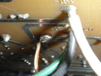
By not being sufficiently cautious (shame on me 😡 first time it happens in decades), in the back of one transistor (other side of the pcb) there is a thin wire (red and white) that was connected to the board. It seems while I desoldered the radiator, the wire moved to the wrong position and I did’t see it.
I grabbed a picture on internet to show you ( wire circle in red) but mine was soldered on the trace below.
Basically the wire was not connected as located on this picture but on the trace below after it slipped.
This burnt one max5437 (smoke and turned red) When I powered it on.
Can you please confirm where this wire should be connected ? ( maybe with a better photo as I cannot find one).
I ordered 2x max5437 and will pick them up today wednesday so would be very nice if someone could tell me that asap so I can fix it appropriately.
Do you think something else could have suffered from putting the wire on the trace below (don’t know what this trace volts is….) ?
thank you all
Hello and happy new year
Does someone still have his ref3 ?
In order to refresh mine, I replaced capacitors in the power supply (same value….), diodes and transistors.
By not being sufficiently cautious (shame on me 😡 first time it happens in decades), in the back of one transistor (other side of the pcb) there is a thin wire (red and white) that was connected to the board. It seems while I desoldered the radiator, the wire moved to the wrong position and I did’t see it.
I grabbed a picture on internet to show you ( wire circle in red) but mine was soldered on the trace below.
Basically the wire was not connected as located on this picture but on the trace below after it slipped.
This burnt one max5437 (smoke and turned red) When I powered it on.
Can you please confirm where this wire should be connected ? ( maybe with a better photo as I cannot find one).
I ordered 2x max5437 and will pick them up today wednesday so would be very nice if someone could tell me that asap so I can fix it appropriately.
Do you think something else could have suffered from putting the wire on the trace below (don’t know what this trace volts is….) ?
thank you all
Attachments
Geez Louise, you could have asked a week ago when I had the top off.😉
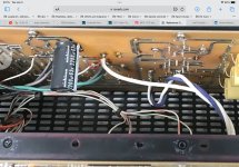
Anyway, I took it off again, see attached.
I can see replacing electrolytic caps, but diodes and transistors if the Ref 3, or any other component is working OK?
Good luck. I'll leave the lid off until 3:00 PM EST if you have any more questions.
S.
Anyway, I took it off again, see attached.
I can see replacing electrolytic caps, but diodes and transistors if the Ref 3, or any other component is working OK?
Good luck. I'll leave the lid off until 3:00 PM EST if you have any more questions.
S.
Attachments

- Home
- Amplifiers
- Tubes / Valves
- Intermittent Static on ARC REF 3 Preamp