I have had a similar issue with my DIY Ref 3. It turned out to be the 6550 tube in the PS. Replaced it and the problem went away.
Interesting comment on the PRP resistors. I used them in both my Ref3 preamps. No problem with either over the last 8 years. What is a "sparking problem"? Kind of vague.
Interesting comment on the PRP resistors. I used them in both my Ref3 preamps. No problem with either over the last 8 years. What is a "sparking problem"? Kind of vague.
I've also had problems with PRP resistors. One became unstable in a tube regulator, causing the regulated voltage to fluctuate wildly. Another one in the cathode circuit of the input stage became noisy. That one only had a couple of volts on it. Since it was a 0.25 watter I suspect the heat and/or mechanical stress (it was soldered to the tube socket) killed it.
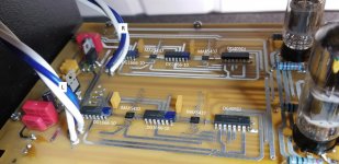
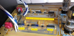
I suspect something isolated to the left channel signal path as the issue is not on both channels, as would be the case if on the power supply board. I was suspecting the FET's, given that the noise sounded characteristic of what I would expect from a leaky semiconductor (I'll attach a sound bite, start at the 30 sec mark). I don't have any of the red resistors - but I saw a post that suggested one of the resistors connected to the plates of the 6H30P tubes, particularly those connected to the +180v rail. I am attaching a picture of the board, with resistor values - the 15K resistors with a red outline around the value text box are connected to the +180v rail.
I'm hoping it's not the FETs as they were defaced by Audio Research, and color coded to indicate that they are a matched pair (note the biasing resistors are different for each - the left bank equates to 187.76 ohms and the right bank equates to 182.02 ohms).
Does anyone have a service manual for the Audio Research Ref 3, showing 1) the source/model/make of the FETs, 2) the process on how to bias the FETs, and 3) a source for the specialty 0.0024uF polystyrene caps in series with the signal path (voltage rating/tolerance/where to purchase)?
Where can I purchase OEM matched FETs and polystyrene caps? Also, when changing the volume, I see a temporary DC component on the output - trying to figure out where that's coming from.
In case the pictures and sound file don't upload, I'll also place them on a Google Drive repository: Audio Research Reference 3 Preamp - Google Drive
Thanks for the help folks.
Attachments

Hi Obseedian - in your case, were the resistors open, or just causing noise, but still measuring okay with an ohmmeter?I've also had problems with PRP resistors. One became unstable in a tube regulator, causing the regulated voltage to fluctuate wildly. Another one in the cathode circuit of the input stage became noisy. That one only had a couple of volts on it. Since it was a 0.25 watter I suspect the heat and/or mechanical stress (it was soldered to the tube socket) killed it.
The 6550 is probably not the problem. But it is interesting to note that the noise was only in one channel both times I had to replace the power tube. My thinking is that the whole PS is losing its ability to hold the voltage. But the channels have a slight difference in the sensitivity to the fluctuation so one starts to have problems before the other. Just guessing here.
I have never found out what FET ARC used or how it is biased. A fellow member of the forum helped me pick a FET and set the bias. I found that the higher the current from the FET the brighter the sound became.
The temporary DC might be normal. It could be caused by the volume chip not having zero crossing detection and compensation. How long does the DC last? I will see if I get the same thing.
any ones in particular I should focus on?
Could be any of several locations, but the most likely source of noise is the first plate resistor.
a source for the specialty 0.0024uF polystyrene caps in series with the signal path
(voltage rating/tolerance/where to purchase)?
ARC uses house part numbers, and you'd have to buy parts directly from them.
The 2400pF is a standard value, but they test and screen all parts.
It's not likely the this capacitor needs to be, or should be, replaced.
Last edited:
Thanks. I went ahead and purchased a nice scope, thinking I could more easily isolate the source of the noise, but that turned out not to help in the least. the left channel looks identical to the right channel🙁.
So I reverted to swapping more L & R components, still no luck. Here's what I've swapped so far: On the Preamp board (PWB653E):
- Both 6H30P tubes (L with R) - Both 15K ohm plate resistors with both measured correctly when out of the circuit (L with R) - Both 10uF (C6 and C7) caps (the big ones at the end of the signal path) - Both 2400pF (C11 and C12) polystyrene caps (one of the end on one of these was not connected to the foil, so I re-soldered it, but really would prefer to replace it). - The LM337 and LM317 regulators on the preamp board - All electrolytics on the preamap board - Touched up many solder connections
On the Power Supply board: - All LM337, LM317 and LT-1085 regulators were replaced (one of the LM317s was defective, so I figured I might as well replace them all, given the age). - All electrolytic caps were replaced - re-soldered most of the board - DeOx'd all connections
I suppose, this leaves it to either: - the FET's (interesting, I expected to see a signal on the FETs, but they just seem to be for DC biasing of the tube - no AC visible on either channel - the digital volume network - the digital switching network (but the issue is not isolated to any particular source, so not likely)
The noise "sounds" like what I'd expect from a leaky semiconductor. That's a shame because those matched FETs/digital volume components don't appear to be something I can replace (AR won't sell them to me).
I'm just trying to help fix this for a friend - didn't want to let him down.
Very interesting... well, it's not the FET's either... I swapped the L & R FETs (and their biasing resistors) and the noise remains in the L channel.
The parts for the digital volume control are still available. The DS1666 parts are EOL, but are still out there. The other chip is the common DG409. The circuit diagram is basically the same as the Ref 2 MII which is published at ARCDB - The Audio Research Database - The unofficial & unauthorized source for ARC information
Where is the LT-1085 used on the PS board.
I assume that the noise stays in the left channel no matter how the Mono and Invert controls are set?
Where is the LT-1085 used on the PS board.
I assume that the noise stays in the left channel no matter how the Mono and Invert controls are set?
Thanks johnmarkp. I made assumptions on the REF 3, based upon the REF 2 MII and just eliminated the negative feedback FET circuitry from the REF 2 MII to create what I suspect is representative of the REF 3 (attached), showing one channel. The MII used 4 digital resistor IC's and the REF 3 uses 2 but adds two digital potentiometer IC's, so it's a little different, but similar enough. I left the Digital resistor/pot and mux the same as on the MII.
So it appears that a test I could do, would be to lift the 1K leads from each, the negative (DG409 pin 9) and positive (DG409 pin 8) input resistors and run a cross wire to swap the L & R signals?
If if the noise transfers to the R channel, it is clearly one of the following:
- MAX5437 (Digital Pot), https://datasheets.maximintegrated.com/en/ds/MAX5436-MAX5439.pdf
- DJ409 (Dual 4 channel differential Analog MUX), https://www.vishay.com/docs/70062/dg408.pdf
- DS1666 (Digital Resistor), https://datasheets.maximintegrated.com/en/ds/DS1666.pdf
If not, I wonder if it is a tube biasing issue? But swapping the constant current FET's didn't change anything.
I wasn't provided the remote, so I can't check if the issue remains in Mono or with Inverted phase.
hmmm...
Here are some additional pictures, FYI. The LT1085 is on the power supply board, shown in picture.
Ok, so it's clearly coming from that digital trim-pot/differential analog Mux/digital resistor array on the left channel. I lifted in input side of all of the 1K resistors [the negative side (DG409 pin 9) and the positive side (DG409 pin 8) from each channel] and criss-crossed wires to route the circuit board L volume stage to the R side of the preamp tube stage, and visa versa.
The noise followed and is now on the right channel. So it's clearly one of the two MAX5437's (Digital Pot), or the DJ409 (Dual 4 channel differential Analog MUX) or one of the two DS1666's (Digital Resistor).
Looks like the DS1666-010's are matched (marking on them), but I suppose unmatched pairs will certain sound better than the noise.
The noise difference between the two channels is significant with an average difference of 10dB and with the spikes in the noisy channel, a difference of 16dB.
I'm surprised I couldn't find trace the noise with the scope... one would think it would be visually obvious.
I will update when I figure out which specific one went bad.
Any ideas on how I can get ahold of matched sets of the above and of the 0.0024uF polystyrene caps? I suppose the caps should be rated at least at 100V.
Attachments


Hi Obseedian - in your case, were the resistors open, or just causing noise, but still measuring okay with an ohmmeter?
The cathode resistor measured fine, the staged biased up correctly but just got noisy. The resistor in the regulator (in the feedback network) measured fine too, but once it had voltage across it, it became unstable. Had to replace them to know that's what the problem was.
Any ideas on how I can get ahold of matched sets of the above and of the 0.0024uF
polystyrene caps? I suppose the caps should be rated at least at 100V.
ARC is the proper parts source.
Thanks. Yes, ARC would be best, but they said they would not sell direct - they want me to send the unit in for repair. 🙁
Does anyone have a service manual for the Audio Research Ref 3, showing 1) the source/model/make of the FETs, 2) the process on how to bias the FETs, and 3) a source for the specialty 0.0024uF polystyrene caps in series with the signal path (voltage rating/tolerance/where to purchase)?
1. Of course not. Why would you expect ARC to deface them if the types were in the service manual?
Otoh this is not rocket science, far from it. Donkey years ago i drew a circuit, made some assumptions and put values to the currents. If you have a working unit you can just measure the current as this is a simple CCS. Cannot see a reason many other fets won't work just as well. I think i built it using a 2sk170.
2. Look at the circuit. All voltages and currents are assumed, never bothered to update those with real readings as i long lost interest in this particular circuit or anything else wearing the ARC badge.
3. No idea where this cap is and what is it doing. Cannot see any reason for wanting this exact value. Is it just bypassing one of the output caps?
The DS1666 blow up all the time, mostly because users connect tube dacs or phono stages and this often puts the input at an elevated voltage. A pretty dumb choice on the part of ARC.
Attachments
Analog_SA, That looks familiar🙂
Vsquared, got my ARC units mixed up. I think they went to the Max part since it can take higher input voltage compared to the DS1666. They used the Max5437 / DS1666 combo for a long time, Ref3, 5 and 5SE. The Ref 6 uses different parts. I do not think matching new DS1666's is critical. I took the time to measure 20 different volume chips a while ago. The difference between the lowest and highest value was less than 1db.
Vsquared, got my ARC units mixed up. I think they went to the Max part since it can take higher input voltage compared to the DS1666. They used the Max5437 / DS1666 combo for a long time, Ref3, 5 and 5SE. The Ref 6 uses different parts. I do not think matching new DS1666's is critical. I took the time to measure 20 different volume chips a while ago. The difference between the lowest and highest value was less than 1db.
...arg... well, I replaced the DG409 and both DS1666-010's in the left channel and no luck... arg...
Guess I'll try the last two in that path, the MAX5437's, next... after that, I've pretty much run out of things to replace...
Guess I'll try the last two in that path, the MAX5437's, next... after that, I've pretty much run out of things to replace...
Attachments

Last edited:
Analog_SA, That looks familiar🙂
10 years John. Can you believe it?
Guess I'll try the last two in that path, the MAX5437's, next... after that, I've pretty much run out of things to replace...
Have you considered the tube sockets?
Well folks, this closes the chapter for the culprit of the background noise in the left channel... it turned out to the the Maxim MAX5437 Digital Potentiometers... They were not at all fun to replace, being surface mount devices, but we're all good now. And as for the 2400pF Polystyrene decoupling caps that was seeking, I went with the REL RELCAP-51620, 600v RTE caps from Parts Connexion and had them match all 4 for me. So we're good to go... finally.
Attachments
- Home
- Amplifiers
- Tubes / Valves
- Intermittent Static on ARC REF 3 Preamp