Michelag,
Quick question - are you considering building the PSU into boards as the original designer did - I am intending to do something along those lines not only to better layout but also spend additional time on planning on checking. Do you know what sort of process would be adequate to implement to make these boards considering the voltages at B+ from power transformer?
Hi...
I just finished another project today... In a few days my daughter should be born... So mind and arms are dedicated to something else...
However, yes, i think about boards, easier to build and to inspect, and to layout with heatsinks and cables...
What do you mean with process to implement to make the boards?
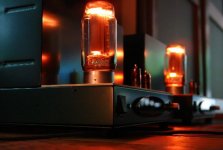
Have a look at the pictures, it is pretty straightforward what their function is...
And remember, the audio case has coleman filament regulators...
Still have to think about cases and couple of things...

Congratulations! Other priorities indeed!
Agreed the functions/layout are very logical - thank you for sharing this layup, definiltely very helpful.
I guess the question, more specifically is that these look like etched boards - to my eye - but I was concerned about the safety of the boards at high voltages - obviously the 800+ line being the true concern.
Same schematic or another one? Yours are copper plates, right?Nice tube- even nicer sound!
Yes, i think about using come epoxy compound or resin to insulate contacts and solder joints... Think should be enough... I don't trust PCBs at 1kV...Congratulations! Other priorities indeed!
Agreed the functions/layout are very logical - thank you for sharing this layup, definiltely very helpful.
I guess the question, more specifically is that these look like etched boards - to my eye - but I was concerned about the safety of the boards at high voltages - obviously the 800+ line being the true concern.
Graphite. Shindo schematic.Same schematic or another one? Yours are copper plates, right?
So interstage transformers?Graphite. Shindo schematic.
Your build or bought?
Last edited:
Suppressor grid is grounded, i see.
What's the point in leaving if floating with a capacitor soldered in?
Hi guys,
I am the original designer of this amp, sorry I haven't seen this thread earlier, I stopped doing DIY audio some time ago.
This amp has worked OK for the last 5 years, no problems! 🙂
About the DC "floating" grid - I had found an article about this years ago, I did some sound A/B tests with headphones and I liked indeed the sound with this connection.
I have always preferred the sound of copper plate GM-70 s in this amp, which is unfortunate, given their price and availability.
For the preamp tubes, I originally used D3a, but I like the sound of E186F more - even if they have less voltage swing.
I was thinking of a design for a safety feature on these kind of amplifiers. I got a bunch of thyristors and gate trigger transformers. I was thinking of series connected electrolytic. with parallel thyristors+resistors.
You then have a 555 that drives the transformers through a NPN, and puts out a pulse train when the 6.3 is disabled.
You then have a 555 that drives the transformers through a NPN, and puts out a pulse train when the 6.3 is disabled.
So there's a separate on/off switch just for filaments? by looking at the enclosure this doesn't seem to be the case?
I think that sw4 is again a current inrush limiter for the filament transformer primary, that then bypasses NTC1... perhaps i'm wrong...
what is going to be a significant closing time for tempo? 3 seconds? 10 seconds?
so, what are the possible switches/relais that arduino controls? I looked at the PSU inside but no hints... they have to be circuit breakes though
I used a couple of big and heavy toroidal transformers for the PSU (custom made transformers, with electrostatic shield), and these have a significant inrush current: this is why I have used two relays (Arduino controlled) that short out the inrush resistors after one second or so. If you use classic transformers, this protection might not be needed.
The third relay (temporization) turns on high voltage after around 20 seconds, when the filaments would have heated up. The DHTs do not need this precaution, but the preamp tubes do. As Rod said, the HV PSU voltage is slow-rise by design. The PSUs are stabilized, not regulated, by the way (this is very important).
The bottom of the 1100V PSU PCB is covered in Epoxy, and I should have mentioned on the blog that this circuit part should absolutely not be touched/adjusted while the power is on...
Last edited:
Hi, my pleasure to read from you!!!I used a couple of big and heavy toroidal transformers for the PSU (custom made transformers, with electrostatic shield), and these have a significant inrush current: this is why I have used two relays (Arduino controlled) that short out the inrush resistors after one second or so. If you use classic transformers, this protection might not be needed.
The third relay (temporization) turns on high voltage after around 20 seconds, when the filaments would have heated up. The DHTs do not need this precaution, but the preamp tubes do. As Rod said, the HV PSU voltage is slow-rise by design. The PSUs are stabilized, not regulated, by the way (this is very important).
The bottom of the 1100V PSU PCB is covered in Epoxy, and I should have mentioned on the blog that this circuit part should absolutely not be touched/adjusted while the power is on...
I have got many many questions about your project, hope you'll have some patience to help me...🙂
Starting from scratch, what are the three relays used?
Are enclosures from hifi2000?
Did you program the Arduino yourself?
Please i need some answer Vincent...
Thank you!
The bottom of the 1100V PSU PCB is covered in Epoxy, and I should have mentioned on the blog that this circuit part should absolutely not be touched/adjusted while the power is on...
Even at 4-500 volts I don't adjust anything while it is powered on. Better take 10 minutes to adjust and turn stuff back on than to kill yourself. But what epoxy did you use for that?
Vincent! What a pleasure to have you chime in - thank you for your design and your generosity. I know we'll have plenty of questions and I only hope you'll bear with us!
Agreed with the comments - I was interested in designing some PCBs, similarly broken down the way you made yours - single layer with a heavy copper trace if it would be safe/logical - It would also be nice to offer these for anyone's project and to some extent build the amp with some modularity.
I was looking to have the transformers wound by the folks at Audiophonics in Bordeaux - anyone have experience with them?
A few doubts if you'll indulge us:
1) D17 and 18 - arent specified in your schematic (8V heater line) - I would assume that the SB360 carries through?
2) LED 3 near the Arduino doesnt have R22 specified, i'd imagine this is what we'd assume in the calc.
3) - your two test points visible on the sides of the GM70's on the chasses - are those access to TP1 and TP2 for biasing?
4) any preference for Cap at position C4? It looks like you used some nice Russian PIO's for C5 .
Please do share more info on that epoxy you chose - is the copper weight on these boards above 2oz?
Gracias!
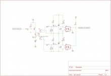
Sorry for blurting out my own projects through this topic, i'm working on a complete amplifier control module not unlike this.
Heres a schematic i made for a "Building block" around the high voltage capacitors.
I wanted to make sure that the amplifier would detect all the errors internally, and also measure for possible danger/fault conditions. I thought discharging a cap bank with bleeders/equalisation resistors was a bad idea, so i'm designing a triple redundant system so no-one gets killed.
Attachments
Hi, my pleasure to read from you!!!
I have got many many questions about your project, hope you'll have some patience to help me...🙂
Starting from scratch, what are the three relays used?
Are enclosures from hifi2000?
Did you program the Arduino yourself?
Please i need some answer Vincent...
Thank you!
Hi!
Yes, the enclosures are from HiFI2000. Very good quality! The top plate is custom, cut and engraved by https://www.schaeffer-ag.de/ .
The relays are SPST, mains rated, contacts for at least 3A, coils for 6 volts.
I programmed the Arduino. The firmware is attached below.
Attachments
Even at 4-500 volts I don't adjust anything while it is powered on. Better take 10 minutes to adjust and turn stuff back on than to kill yourself. But what epoxy did you use for that?
Of course 🙂 It's common sense, but worth reminding...
I used quick set 2-component Epoxy glue (found at home improvement stores). It's thick enough to stay where you put it until it dries.
Vincent! What a pleasure to have you chime in - thank you for your design and your generosity. I know we'll have plenty of questions and I only hope you'll bear with us!
Agreed with the comments - I was interested in designing some PCBs, similarly broken down the way you made yours - single layer with a heavy copper trace if it would be safe/logical - It would also be nice to offer these for anyone's project and to some extent build the amp with some modularity.
I was looking to have the transformers wound by the folks at Audiophonics in Bordeaux - anyone have experience with them?
A few doubts if you'll indulge us:
1) D17 and 18 - arent specified in your schematic (8V heater line) - I would assume that the SB360 carries through?
2) LED 3 near the Arduino doesnt have R22 specified, i'd imagine this is what we'd assume in the calc.
3) - your two test points visible on the sides of the GM70's on the chasses - are those access to TP1 and TP2 for biasing?
4) any preference for Cap at position C4? It looks like you used some nice Russian PIO's for C5 .
Please do share more info on that epoxy you chose - is the copper weight on these boards above 2oz?
Gracias!
Thank you!
1) D16..D18 are protection diodes, can be 1N4001 or of course SB360.
2) R22 depends on the LED type you are using. Calculate using the formula (6 - Vf) / 0.01 . Using my firmware, this led is dimmed down during normal amp run, and it's bright only during fault conditions.
3) exactly. These are jacks allowing me to measure and adjust the bias and the GM70 heating voltage (necessary when you swap tubes) without opening the chassis - the trimmers are also accessible through small holes in the top plate.
4) at that voltage rating, we don't have many choices. I used Wima DC Link MKP. C5 are indeed NOS Russian PIOs! They are physically huge for their capacity...
5) I loaded the copper traces with a lot of solder where necessary (low impedance / high current circuits). I etched the PCBs myself, so they were bare copper, without solder mask.
Last edited:
I built this amp in 2014-2015... wow, time flies.
Things I would improve today:
- biasing the driver tubes with series SiC Schottky diodes like C3D02060F
- try replacing the CCS driver anode loads with Ale Moglia's hybrid mu-follower circuits for lower output impedance (higher circuit complexity, though)
- the CCS biasing circuit sounds great. BUT it's not the most stable: it depends on the circuit's temperature. It stabilizes after 10 minutes or so, but I would try using Rod Coleman's shunt fixed bias regulators instead.
- in the B+2 power supply, one could use a better/more modern CCS for the voltage reference
Last edited:
- Home
- Amplifiers
- Tubes / Valves
- Interesting GM70 scheme... Some questions on the PSU, who helps me please?