It is just idea to make switch which can be controlled by .step command, to show on one graph amplifier responses for different source types, or select multiple feedback networks to amplifier to see resulting response etc.The lack of response is certainly not due to lack of interest.
I think it is because many of us (like me) don't understand what you are doing.
Can you explain?
Jan
The SWeq switch made by me, which has two parameters, is suitable for your case. When the parameters are equal, the switch is closed (has low resistance). Using it, you can change the configuration of the circuit using STEP. I came up with a scheme to observe the noise of different circuits simultaneously.
Attachments
I wonder if the "fra" or "fraprobe" are just for use with SMPS, or can they be used with linear regulators and amplifiers.
If you open the example fra_eg1.asc in ...\AppData\Local\LTspice\examples\Educational\FRA you will see it used on a linear op-amp. The FRA folder in the older version of LTspice just uses AC sources and does not recognize the fra symbol. I'm not sure what advantages it provides? Anyone know?


This circuit and/or the standard "probe" provide the OLG as is, by plotting V(A)/V(B). The OLG determines the portion of the stimulus on either side of it. For example, if the OLG was 99 then V(B) would be 1% and V(A) would be 99%.
Hi, I have LTSpice ver. 24.1.4 and I have some issues:
- fourier analysis syntax has changed and I have to remove last digits;
- I don't know how to save extra models of leds, mosfets, fets, etc... to avoit them to be deleted at every model update;
- add potentiometers that were working on previous versions.
The 24.1.x branch of LTspice is riddled with bugs and new parsing rules that break a lot of existing .asc files. There is a discussion on the LTspice forum at Groups.io about this. See link below.
LTspice on Groups.io
Many users (myself included) have uninstalled version 24.1 and reverted back to 24.0.12, which does not include the new behaviors and bugs of the 24.1 branch. This is what I suggest doing until someone can verify that these new problems have been fixed.
LTspice on Groups.io
Many users (myself included) have uninstalled version 24.1 and reverted back to 24.0.12, which does not include the new behaviors and bugs of the 24.1 branch. This is what I suggest doing until someone can verify that these new problems have been fixed.
Thank you @Ray Waters , I will draw a potentiometer by myself to add it again to the files.
I will search the old link to download reinstall that one.
Any info on how to add my own models without having tham canceled at every update of the database?
I will search the old link to download reinstall that one.
Any info on how to add my own models without having tham canceled at every update of the database?
I have copied this aikido circuit into a LTSpice model, however, when I run it I get an error message. I'm new to this it is one of my first LTSpice models.
I've posted the file. If anyone would like to run it as help me determine what I did wrong, I'd appreciate it. Feel free to modify and use it if you wish. Thanks.
I've posted the file. If anyone would like to run it as help me determine what I did wrong, I'd appreciate it. Feel free to modify and use it if you wish. Thanks.
Attachments
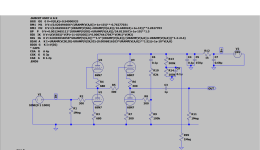
You have used symbols for C5 and C7 that include a lot of parameters, some of which LTspice doesn't like. If you delete all of those extra capacitor parameters, leaving only the capacitance itself, these errors will go away. LTspice doesn't need them to perform a simulation anyway.
The floating node errors flag that there is no DC path to ground at the grid of U3 (node 3) or the plate of U4 (node 8). This is just the way that the Aikido circuit is drawn so you can ignore these warnings.
Finally, you are running the transient analysis for a full 5 seconds. 5 milliseconds (5m) is enough to display 5 complete cycles with a 1 KHz input signal
Thanks @Ray Waters. I made those changes. I will ignore the floating node errors.
Another questions I have. I'm getting +/- 10V on V(out). This seems high to me for this circuit using 6sn7 tubes for input and output. Any idea as what could cause this high output voltage?
I think I had my input too high. I adjusted my input from 1V amplitude to 0.1V. I'm seeing a gain of 10 which is expected from this circuit.
Last edited:
The Aikido circuit has a fixed gain related to the tube used. Specifically, the circuit gain is going to be approximately 1/2 of the amplification factor (mu) of the tube used in the first stage. The 6SN7 has a mu of about 20 so the gain is going to be half of that, or about 10 as you observed. A high mu tube like the 12AX7 will have an insane amount of gain if the circuit is intended to be used as a line stage.
There are ways to reduce the gain of an Aikido circuit. One is by applying feedback but this isn't recommended unless you know what you are doing. John Broskie suggested attenuation between the first and second stages as described in the following article. See the section titled "Lowering Line-Stage Gain" near the bottom of the page. He shows how to obtain a gain of 12 dB (x4) for several circuit configurations, including the Aikido.
Lowering Line-Stage Gain
Note also that the Aikido is an inverting circuit. This may or may not be important but is something to be aware of.
This was my first LTSpice model and I want to make sure I was using it correctly.
Thanks Ray for providing the link. Yes, I would like to drop gain on the aikido preamp to match better with my power amp. I may follow the 12 dB gain Broskie outlined in his article.
Thanks Ray for providing the link. Yes, I would like to drop gain on the aikido preamp to match better with my power amp. I may follow the 12 dB gain Broskie outlined in his article.
The 24.1.x branch of LTspice is riddled with bugs and new parsing rules that break a lot of existing .asc files. There is a discussion on the LTspice forum at Groups.io about this. See link below.
EDIT... found it 🙂 Next post.
I've just updated my installation for curiosity and have one issue I can't figure out. Every sim comes back with the same error that a TIP2955 model is 'undefined' yet it works perfectly in previous versions. The .asc doesn't have to even include this device to throw the error up.
If I delete the TIP2955 from my cmp folder and substitute with another all sims run OK.
The code below is a notepad version of my own custom CMP folder bjt list and I can't see any reason why it fails on this one device. Remember this worked in past versions. Delete this one entry and all seems OK. Why this one is picked up with an error I have no idea. The TIP41/42 models are just as a comparison and work fine.
What is 'Undefined' about it?
Code:
.model TIP41C NPN (IS=7.55826e-11 BF=260.542 NF=1.11221 VAF=100 IKF=0.526814 ISE=1e-08 NE=2.18072 BR=26.0542 NR=1.5 VAR=1000 IKR=3.54059 ISC=1e-08 NC=1.63849 RB=4.56157 IRB=0.1 RBM=0.1 RE=0.0162111 RC=0.0810556 XTB=0.1 XTI=1 EG=1.206 CJE=1.93296e-10 VJE=0.4 MJE=0.259503 TF=1e-08 XTF=4.06972 VTF=7.1157 ITF=0.001 CJC=1.09657e-10 VJC=0.730921 MJC=0.23 XCJC=0.803085 FC=0.8 TR=9.01013e-08 PTF=0 Vceo=100 ICrating=6 mfg=ON_Semi)

.model TIP42C PNP (IS=5.65618e-10 BF=120.073 NF=1.24004 VAF=90.6071 IKF=1.46498 ISE=6.98929e-14 NE=4 BR=2.83268 NR=1.30331 VAR=27.1221 IKR=10 ISC=6.98934e-14 NC=3.78125 RB=4.71382 IRB=0.234602 RBM=0.12691 RE=0.000666374 RC=0.0927424 XTB=3.21145 XTI=1 EG=1.05 CJE=1.93221e-10 VJE=0.4 MJE=0.259369 TF=9.99163e-09 XTF=4.41941 VTF=6.53488 ITF=0.001 CJC=1.0962e-10 VJC=0.731968 MJC=0.23 XCJC=0.799902 FC=0.799995 TR=1e-07 PTF=0 KF=0 Vceo=100 ICrating=6 mfg=ON_Semi)

.model TIP3055 NPN(IS=4.66p BF=360 VAF=100 IKF=0.25 ISE=3.339E-11 BR=2 ISC=5n RB=3 IRB=0.001 RBM=0.4 RC=0.04 CJE=5.802E-10 VJE=1.2 MJE=0.45 TF=8E-8 XTF=1 ITF=3 PTF=120 CJC=2.121E-10 MJC=0.4 TR=2.55E-6 XTB=1 VCEO=100 ICRATING=15 MFG=TEXAS)

.model TIP2955 PNP(IS=4.66p BF=360 VAF=100 IKF=0.25 ISE=3.339E-11 BR=2 ISC=5n RB=3 IRB=0.001 RBM=0.4 RC=0.04 CJE=5.802E-10 VJE=1.2 MJE=0.45 TF=8E-8 XTF=1 ITF=3 PTF=120 CJC=2.121E-10 MJC=0.4 TR=2.55u XTB=1 ) VCEO=100 ICRATING=15 MFG=TEXAS)
Last edited:
How weird, I've just spotted something at the last moment... there is a 'close bracket' symbol in the line. That never through an error up with past versions.
As the two previous messages suggest, "what is undefined about it" is the character string VCEO=100 after the right parenthesis.
The right parenthesis tells the LTSPICE parser that's the end of the .MODEL statement but then there are more characters after the end.
Apparently it doesn't matter whether that particular .MODEL happens to be used in the simulation or not; the parser reads the model library, encounters undefined/illegal stuff, and raises an error flag.
- Home
- Design & Build
- Software Tools
- Installing and using LTspice IV (now including LTXVII), From beginner to advanced