For really 'grokking' these things you need to get away from the idea that this software app somehow is aware of electronics and does mysterious things to electronic parts. It's not and it does not. It's just a bunch of instructions some programmer threw together instructing it how to process numbers it is fed, and how to present the outcome of that processing.
The ultimate realization of this is a spreadsheet. A spreadsheet is a very, very flexible framework that can do all sorts of things manipulation numbers. It does not matter what the numbers represent, amperes current in a resistor or the number of cucumbers consumed per day in Iceland. The numbers don't care.
Anyone who understands Excell and electronics can write his own circuit simulator. Once you understand this, you can make it jump through all sorts of hoops.
Jan
So say you have a drawing of a little dog, with three of its legs called 'P', 'bread' and 'jojo'. Its name is irf530, and you have a file irf530.mod, with the 1st line: '.model irf530 P bread jojo' that will work fine*.
Now read it again ;-)
Jan
*of course the names must be in the right order for the model, normally G D S, so the dog leg P is the gate, bread is the drain and jojo is the source.
Uhhhh
of course the names must be in the right order for the model, normally G D S . . . .
However that's not quite the correct ordering(!)
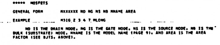
BJTs are C B E and MOSFETs are D G S
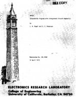
The authoritative reference is Larry Nagel's thesis; he wrote the original SPICE program and got a Ph.D (Don Pederson was his advisor) for the research. UCBerkeley reprinted his thesis as a technical Memorandum, which they included as part of the package whenever they gave away a copy of the source code. Screen capture images below.
_
Attachments
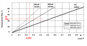
I opened this metal film resistor datasheet and found an incredibly useful figure that I've copied as an attachment, below. It quantifies something we already know, but tend to forget: when a resistor dissipates power, it heats up. When it dissipates a lot of power, it gets very hot! And there are the numbers, in that figure.
To choose an appropriate wattage rating, the circuit designer must
EXAMPLE
Suppose we have a resistor whose power dissipation is 250 mW. Suppose we will allow its body temperature to rise up to 70 degrees C, hot enough to burn a finger after 5 seconds. This is (70 - 25) = 45 degrees C above the ambient air temperature of 25C.
We draw a vertical red line at 0.25W and a horizontal red line at 45 degrees C. They intersect at a point where a 500mW resistor curve would go. So we choose a 600mW resistor and sleep soundly.
NOTICE that the circuit designer in this hypothetical example has chosen to let the resistor get very very hot. But in real life, you may not be so lenient. You may insist that no component can get hotter than 60C; or whatever your human judgment feels most comfortable with.
_
To choose an appropriate wattage rating, the circuit designer must
- Calculate the average power (over a 1 second averaging window) that the resistor will dissipate
- Draw a vertical line on the datasheet curve, at this power dissipation
- Make a human judgment decision: how hot is too hot? What temperature will we allow the resistor body to reach? How many degrees C above the ambient air temperature?
- Draw a horizontal line on the datasheet curve. at this temperature rise above ambient air.
- Choose the resistor rating equal to or greater than the intersection of those two red lines.
Suppose we have a resistor whose power dissipation is 250 mW. Suppose we will allow its body temperature to rise up to 70 degrees C, hot enough to burn a finger after 5 seconds. This is (70 - 25) = 45 degrees C above the ambient air temperature of 25C.
We draw a vertical red line at 0.25W and a horizontal red line at 45 degrees C. They intersect at a point where a 500mW resistor curve would go. So we choose a 600mW resistor and sleep soundly.
NOTICE that the circuit designer in this hypothetical example has chosen to let the resistor get very very hot. But in real life, you may not be so lenient. You may insist that no component can get hotter than 60C; or whatever your human judgment feels most comfortable with.
_
Attachments
Last edited:
Guys, I lost my current probe. I still have the red voltage probe, but when I hover the cursor over a component I no longer have the current probe. I have a hand with pointed index finger.
Have I inadvertently turned off the current probe? How do you do (and undo) that? Thx
Have I inadvertently turned off the current probe? How do you do (and undo) that? Thx
Same here, I didn't see any updates load......
The data is still there (operating point and dissipation) on the status line, but the little picture of the clamp-on meter is gone.
The data is still there (operating point and dissipation) on the status line, but the little picture of the clamp-on meter is gone.
Last edited:
...The data is still there (operating point and dissipation) on the status line, but the little picture of the clamp-on meter is gone.
I don't get that. The status line at the bottom says "Right click to edit R1" or whatever component I'm over.
hi,
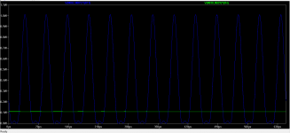
A resistor in a power amp is dissipating power like attached (R11).
What power rating resistor should I use for all practical purpose ?
regards
prasi
Depends. Is this with full power? Then remember that the average power that a power amp delivers with music is often only 10-20% of it's max power. Music has low average level.
Mark mentioned an average 1 sec value; that value will be (much) less than what you show, assuming you show at max power. In your case, I would be very comfortable with 0.5 or 0.4W resistors.
BTW Mark's curves are for very specific resistor types, and not all resistors are created equal in this respect.
Jan
Last edited:
Guys, I lost my current probe. I still have the red voltage probe, but when I hover the cursor over a component I no longer have the current probe. I have a hand with pointed index finger.
Have I inadvertently turned off the current probe? How do you do (and undo) that? Thx
This was what I also have and did post?, mine it was the component lib IRF mosfets, do sim nice but no current probe, did use 0.1 ohm resistors for that, this did work.
Do you have the waveform window open ?
It doesn't matter. It does the same thing after a dc sim (no waveform window) and ac sim (window open).
Guys, I lost my current probe. I still have the red voltage probe, but when I hover the cursor over a component I no longer have the current probe. I have a hand with pointed index finger.
Have I inadvertently turned off the current probe? How do you do (and undo) that? Thx
I fired up LTSpiceIV which I still have. Using the same schematic, I can hover over components and it will show the dc parameters (current and power). It has a pointing hand, not the black current probe. But it does work. Same circuit in version XVII does not.
Anyone have a clue as to what could cause the current probe to become disabled? Everything still works correctly otherwise.
Do you have "Save Device Currents" and "Save Subcircuits Device Currents" check boxes ticked under Tools > Control Panel > Saved Defaults ?
Thanks Indiglo. That was it. Apparently the node voltages always get saved but the currents depend on checking the boxes. Still don't know how it got changed, I wasn't even aware of it.
Hi all
Because I have a lot of derfcon1 errors with the opamp models like the opa604 I did use a universal opamp.
However it draws to little current on one side, does somebody now how to correct this? the 604 model does draw 5 mA and the universal just 0.87 mA (on one side by the way the other is 5mA).
With the use of this opamp the defcons are gone.
For the guys with the current probe problems, for some unkwown reason here does it work again.
thanks.
- Home
- Design & Build
- Software Tools
- Installing and using LTspice IV (now including LTXVII), From beginner to advanced