You know more than me on all this 😉
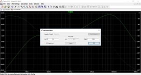
In what context do you mean ? What view do you want grid lines to display on.
In what context do you mean ? What view do you want grid lines to display on.
And one more 🙂
Not sure how I missed your posts before this morning but thank you for the help. Very cool stuff
Dunno on that one. It is the same in LTXVII, greyed out.
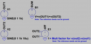
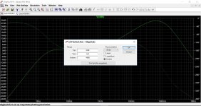
'Tick' is the scaling isn't it ? so log scaling isn't a constant increment like 10, 20, 30 etc, if that makes sense.
'Tick' is the scaling isn't it ? so log scaling isn't a constant increment like 10, 20, 30 etc, if that makes sense.
The spacing on the log scale isn't constant, but surely the software can figure it out, since the X-axis ticks work just fine. Must be a "feature" of LTSpice. 🙂
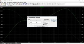
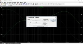
X axis is greyed out for me when selecting log (last image). I can't see how you could enter a setting for 'log' because ech increment goes up by a power of ten. You can set the upper and lower limits though.
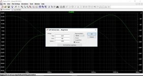
Some of the other settings seem a bit odd, as if it doesn't like some values 😀
Some of the other settings seem a bit odd, as if it doesn't like some values 😀
Attachments
Node 0 in subcircuit converted?
Almost all subcircuits have an internal node 0 as the 'ground' node for that particular circuit.
But what happens when you use for instance an opamp that floats with Vcc=200V and Vee=170V? In real world that would work fine (assuming the input/output signal common mode is respected).
I had some problems with such a circuit in my previous sim as it kept some internal subcircuit bias R's and generators referred to gnd which now is 170+V away of course.
In LTspice is seems to work, so I wonder is LTspice *somehow* modifies the internal node 0 to *some* circuit node that can float with power supply?
Anyone knows about this?
Jan
These 'float' problems arise some times, most of the time 'grounding' the floating circuit-part using a 10G resistor will fix the problem/simulation (with [most of the time] no harm done to the result).
I do not know how the net-0 problem is solved for sub-circuits that contain a net-0 and are nowhere connected to the simulated-circuit-net-0 (only indirectly), but it seems (from experience) to be solved, probably all nets in the sub-circuit are made to be relative to the main-simulated-circuit and absolute to the sub-circuit. But (as I said) I do not know this for sure.
I do not know how the net-0 problem is solved for sub-circuits that contain a net-0 and are nowhere connected to the simulated-circuit-net-0 (only indirectly), but it seems (from experience) to be solved, probably all nets in the sub-circuit are made to be relative to the main-simulated-circuit and absolute to the sub-circuit. But (as I said) I do not know this for sure.
From what I remember, a subcircuit just behaves like a set of components added to the netlist. There is never any need for there to be ground in the netlist pins, if a conductive path from it to ground exists anywhere in the circuit it is connected to. Adding global ground nodes to a subcircuit is bad practice unless you are modeling a device which would realistically always have these connections. Now if you make a subcircuit where the pins are connected to a B-source that references a galvanically isolated circuit in the subcircuit, that circuit must have a ground reference otherwise it is floating. LTspice seems to have some logic for choosing a node to be arithmetical ground when no ground is specified, but this doesn't always seem to be used or work right.
Also if your subcircuit has multiple galvanically isolated circuits in it with their own pins, each circuit must have a conductive path to ground somewhere whether it is in your schematic or in your subcircuit.
Also if your subcircuit has multiple galvanically isolated circuits in it with their own pins, each circuit must have a conductive path to ground somewhere whether it is in your schematic or in your subcircuit.
Last edited:
Usually, in subcircuits the zero used is not real. Just LTspice in this case is used as an analog machine. Just need to calculate some expression. Internal zero should not bother you. Why did not you just try to feed your supply voltage? Most likely everything will be fine if you entered the correct scheme.
Wondering whether anyone has posted ready-to-go files (*.asc) of clock, oscillator and/or XO circuits?
Thx!
Thx!
I know this wasn't the problem you've asked, but even if you had a good model, the outputs of the HC08's would be permanently low...since they are AND gates, and one input of each is low, the outputs will always be low.

now...to your question...
Could you use the LTSPICE and component?
just type AND when you instantiate a component.
You'll also have to set the options to get the high level output correct.
Thanks, I did never did this in ltspice, so it was new for me, maybe a compleet component is a better way? because the and is used lifted.
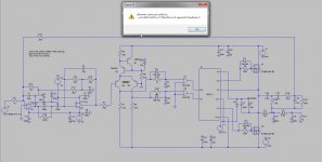
Hi All
I do need the use the 74HC08 but then I get a error as in picture, someone has a model for this digital chip, or now how to correct. be used for dead time generation.
thanks.
I think you need to define a voltage source named "Vcc" to satisfy the operating conditions for the logic gate (e.g. it needs a power supply 🙂)
I think you need to define a voltage source named "Vcc" to satisfy the operating conditions for the logic gate (e.g. it needs a power supply 🙂)
Yes this is just what I did thinking also because in multisim it does the same. still it is maybe a problem because of the use, with -VSS of amp as reference.
Or maybe a gate driver who has dead time implemented, but have no model of them.
Here is a example with a xor gate, adjustable with a pot, I have seen a lot of different approaches.
So I need to read some more.
PWM dead time generator
Last edited:
- Home
- Design & Build
- Software Tools
- Installing and using LTspice IV (now including LTXVII), From beginner to advanced