Use the diode function on your multimeter and make sure the Vbe for the same transistors are within several mV.
Use the diode function on your multimeter and make sure the Vbe for the same transistors are within several mV.
Thanks, I tried matching the Vbe as you said and the distortion reduced significantly (it's become only barely visible, but still exist I believe).
What's the mechanism behind?
...here is your original circuit with two additional resistors added (R10 and R11)...
With this revised circuit, setting R7, R8, R11 and R12 to 22R and still using BC550/560, the output look perfect to my eyes now (I don't have a distortion meter, but it looks perfect from the scope).
Only question remain is that, why LTspice cannot simulate/predict the distortion in the original circuit 😕
If the Vbe are different, the output transistors may be biased too high or too low. The main factor in linearity is the voltage across the output emitter resistors. If too low you get crossover distortion. For class A, 10mV per resistor is optimal based on my experiments. For class AB, 26mV will give the lowest distortion.
The distortion is caused when the output impedance is disrupted as one emitter turns on and the other turns off. With an under-biased stage, the output impedance increases at crossover. With an overbiased stage, it decreases at crossover. In an optimally biased stage, it is the same at crossover as it is at excursions.
The distortion is caused when the output impedance is disrupted as one emitter turns on and the other turns off. With an under-biased stage, the output impedance increases at crossover. With an overbiased stage, it decreases at crossover. In an optimally biased stage, it is the same at crossover as it is at excursions.
Only question remain is that, why LTspice cannot simulate/predict the distortion in the original circuit 😕
Good to hear that you have had some success 🙂
Two main reasons with regard to LT. Firstly the circuit is critically dependent on the slightest change in semiconductor parameters in a way that a much more complex circuit with feedback is not. The reason LT doesn't accurately reflect your experience is because the models are not absolutely representative of your chosen devices.
If anyone has any thoughts on this rather strange occurrence myself and Elvee would be all ears,
http://www.diyaudio.com/forums/software-tools/263590-whats-ltspice-doing-there.html
http://www.diyaudio.com/forums/software-tools/263590-whats-ltspice-doing-there.html
Haven't got the faintest idea, Mooly...
Got a question of my own ...
I tried it before, but never succeeded to get it working in LTspice.
I want to use one Voltage component as the AC power-source (fixed at 50 Hz, rectified and filtered) and an other as the voltage source for the amplifier, all combined in one schematic. I only want to change the frequency the amplifier has to amplify in a simulation (eg. AC analysis).
Questions:
1) Is the basic idea clear?
2) How can I solve this problem?
Thanks in advance...
Edwin
Hi Edwin. I'm not quite sure what you mean tbh. You want to use an AC source as the power supply (and then rectify and filter it ?). That's do-able. You would have to run it as an AC simulation though, not a DC operating point because its a dynamic simulation... if that makes sense.
The other voltage source ? Do you mean the amplifier input signal ?
The other voltage source ? Do you mean the amplifier input signal ?
Mooly,Hi Edwin. I'm not quite sure what you mean tbh. You want to use an AC source as the power supply (and then rectify and filter it ?). That's do-able. You would have to run it as an AC simulation though, not a DC operating point because its a dynamic simulation... if that makes sense.
The other voltage source ? Do you mean the amplifier input signal ?
I want to use both in one schematic.. I'll attach it...
Problems I encounter: It's a disaster to run.. takes till hell freezes over. I do not have that much patience 🙁
Attachments
Last edited:
Easy 
Just a minute......
Sims on AC coupled amps need quite a while to run and settle. That's one issue. I've altered your sim as I've gone along to give you some ideas. Diode bridge... models. I picked MURS320. Had you left those at default ?
Your using some pretty advanced directives for the sim (no problem with that) but I find the long hand easier to follow and so I altered them here.
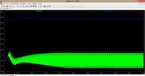
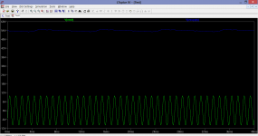
Let the sim run for 1000ms (should complete in a minute or so) and you can see how the amp settles. Now run the sim with an stop time of 1000ms and a start time of say 960ms so that you get just the last 40ms displaying.
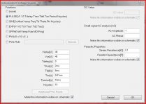
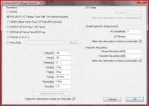
For simulating rails I sometimes set them up as separate AC voltage sources rather than using the full diode + caps circuit. The pictures show typical settings for a split supply.
Edit... I changed the PNP output to one of Bobs models so you need to alter that for the sim to run. Put your own back.
Just a minute......
Sims on AC coupled amps need quite a while to run and settle. That's one issue. I've altered your sim as I've gone along to give you some ideas. Diode bridge... models. I picked MURS320. Had you left those at default ?
Your using some pretty advanced directives for the sim (no problem with that) but I find the long hand easier to follow and so I altered them here.
Let the sim run for 1000ms (should complete in a minute or so) and you can see how the amp settles. Now run the sim with an stop time of 1000ms and a start time of say 960ms so that you get just the last 40ms displaying.
For simulating rails I sometimes set them up as separate AC voltage sources rather than using the full diode + caps circuit. The pictures show typical settings for a split supply.
Edit... I changed the PNP output to one of Bobs models so you need to alter that for the sim to run. Put your own back.
Attachments
Easy
Just a minute......
Sims on AC coupled amps need quite a while to run and settle. That's one issue. I've altered your sim as I've gone along to give you some ideas. Diode bridge... models. I picked MURS320. Had you left those at default ?
Your using some pretty advanced directives for the sim (no problem with that) but I find the long hand easier to follow and so I altered them here.
Let the sim run for 1000ms (should complete in a minute or so) and you can see how the amp settles. Now run the sim with an stop time of 1000ms and a start time of say 960ms so that you get just the last 40ms displaying.
For simulating rails I sometimes set them up as separate AC voltage sources rather than using the full diode + caps circuit. The pictures show typical settings for a split supply.
Edit... I changed the PNP output to one of Bobs models so you need to alter that for the sim to run. Put your own back.
Mooly, thanks for taking the time and putting in some effort..
BTW: I kept Bobs models and just added the library... 😉
The directives were rather a pain to figure out, but I needed some challenge 😀
As far as modelling the power-supply is concerned:
1) usually I just use the Ideal DC supply with some Ri.
2) simulating PS behaviour in conjunction with amplifier-load I also did use the multi- DC-voltage-source with an AC-component, injecting several AC voltages on the supply-line.
3) using the proposed pulse-model might give some additional insight with better performance than a rectified AC-source (which actually takes hours to complete, since LTSpice only uses one processor-kernel for number-crunching).
Some guy suggested me last week to incorporate also the non-linear characteristics of the transformer and the amplifiers in the model....

Hi Mooly,
I'm planning to simulate a Pass F6 before trying to build it, but cannot find the SPICE model for the Jensen transformers, so I tried to create one like below:
.subckt JT-123-FLPCH 1 3 2 4 5 7 6 8
Lpri1 1 3 1119mH Rser=29.8ohm
Lpri2 2 4 1115mH Rser=29.6ohm
Lsec1 5 7 1119mH Rser=29.1ohm
Lsec2 6 8 1116mH Rser=28.8ohm
K Lpri1 Lpri2 Lsec1 Lsec2 1
.ends
A few questions:
- Is this the right way to define a transformer? (this is what I got through Google but isn't very sure)
- The resistance and inductance values above is measured from an actual JT-123-FLPCH at 10kHz, however the inductance measured is very different at 100Hz, 1kHz or 100kHz - so which frequency should be used for the inductance value?
Attachments
Mooly, thanks for taking the time and putting in some effort..
BTW: I kept Bobs models and just added the library... 😉
The directives were rather a pain to figure out, but I needed some challenge 😀
As far as modelling the power-supply is concerned:
1) usually I just use the Ideal DC supply with some Ri.
2) simulating PS behaviour in conjunction with amplifier-load I also did use the multi- DC-voltage-source with an AC-component, injecting several AC voltages on the supply-line.
3) using the proposed pulse-model might give some additional insight with better performance than a rectified AC-source (which actually takes hours to complete, since LTSpice only uses one processor-kernel for number-crunching).
Some guy suggested me last week to incorporate also the non-linear characteristics of the transformer and the amplifiers in the model....
Your welcome. Its all good practice for me too 🙂 The pulse settings I showed actually equate pretty well to what real ripple on a PSU is like. So very useful for checking supply rejection ratios of amplifiers and regulated power supplies.
Modelling transformers is something I haven't done (beyond doing a pulse tranny for triac firing) and tbh I'm clueless on how to set those models up correctly. Once your at that stage with a design I think its time to start thinking of building it for real and see how it performs in the real world.
Hi Mooly,
I'm planning to simulate a Pass F6 before trying to build it, but cannot find the SPICE model for the Jensen transformers, so I tried to create one like below:
.subckt JT-123-FLPCH 1 3 2 4 5 7 6 8
Lpri1 1 3 1119mH Rser=29.8ohm
Lpri2 2 4 1115mH Rser=29.6ohm
Lsec1 5 7 1119mH Rser=29.1ohm
Lsec2 6 8 1116mH Rser=28.8ohm
K Lpri1 Lpri2 Lsec1 Lsec2 1
.ends
A few questions:
Thanks and regards.
- Is this the right way to define a transformer? (this is what I got through Google but isn't very sure)
- The resistance and inductance values above is measured from an actual JT-123-FLPCH at 10kHz, however the inductance measured is very different at 100Hz, 1kHz or 100kHz - so which frequency should be used for the inductance value?
I'll be honest... I haven't a clue on that I'm afraid. Definitely one to start your own topic on and see what help is forthcoming although I'm pretty sure there is a major thread somewhere on PSU's and transformer models ?
If anyone subscribed to this thread knows of it then a link would be good 🙂
Karl, this is the beast, http://www.diyaudio.com/forums/power-supplies/216409-power-supply-resevoir-size.html - everything you wanted to know, or didn't want to know 😀, about modelling power supplies - and it didn't even get into 2nd gear ... 😛
Thanks both, I'll read that thread.
- Home
- Design & Build
- Software Tools
- Installing and using LTspice IV (now including LTXVII), From beginner to advanced