How much ? I didn't noticed any slow down, on my side. Have you at least tried it? If you are right, it seems not complicated to spare-it into 4 generators, commenting the ones that are not in use. I leave you to debate this with its author. It is this kind of remark that could have been constructive if this utopian community project had come into being. This said, I don't see any difference, while I put always in my schematics 3 voltage generators, 1 for sinus, two for this annoying square wave. A question, in the style of yours, what do you propose instead ?
Really? this subject (results degradation when using high dv/dt sources) was discussed a few months ago and resulted in studying different simulator settings (parameters). Please read the thread.
No doubt, the more the computer has to do (the higher the workload) the slower it will be. Adding several high resolution generators will slow down the program execution. As several simulations run for extended time periods (some over an hour) this will make a difference.
..."if this community project had come into being." there is no intermediate result in something that is not born. It seems that some come to answer only to show their spirit of contradiction and to satisfy their aggressiveness.
1000 (or even more) hours study and no (even) intermediate results? Why not start a thread about, what your goals where, what you did find and managed to do and why you did quit the approach, I'm sure we all can learn from it.
Yeah...however, making things simple requires very often much work. Asking that this is being done mainly from thirds can end up likely in a refusal."Why make-it simple when we can make-it complicated ?" ©Shadocks
Link ?Really? this subject (results degradation when using high dv/dt sources) was discussed a few months ago and resulted in studying different simulator settings (parameters). Please read the thread.
%?As several simulations run for extended time periods (some over an hour) this will make a difference.
Working on various designs, not only concentrated on LTspice. As I said, it is just a tool for me, not a goal. Because i loose too much time during those works on repeating the same boring and uncomfortable processes in LTspice, I had this (bad ?) idea to to automate those repeated changes of parameters and options writing , via a graphical interface.1000 (or even more) hours study and no (even) intermediate results?
Anyway, it is wasted time to discuss about this idea. No one is interested here,
It turns into a personal attacks, EOT for me and welcome, FdW, in my ignore list.
Don't worry, you or your children will soon have to fight for their oxygen.
The savages catch things that are within their reach for their own profit, the others try to transform the world in their image."
Yes, you are eminently placed to recognize a personal attack.
Jan
Link ?
Sorry, but backtracking this stuff takes some doing 🙂
It all starts about here #1167 https://www.diyaudio.com/forums/sof...ltxvii-beginner-advanced-117.html#post5428204
And it ends neer post #1360 (or even beyond).
This questing can not be answered, there are to many parameters involved. The '%' may vary from insignificant to large, depending on what is simulated, what the resolution is and the size of the model being simulated. In addition to that, setting(parameters) may/will be of influence and this can also vary from neer-to-nothing up to intolerable-to-watch 🙂
Working on various designs, not only concentrated on LTspice.
Don't we all.
As I said, it is just a tool for me, not a goal. Because i loose too much time during those works on repeating the same boring and uncomfortable processes in LTspice, I had this (bad ?) idea to to automate those repeated changes of parameters and options writing , via a graphical interface.
This should not be needed, especially with the long term experience that you indicate, luckily you found this thread.
Anyway, it is wasted time to discuss about this idea. No one is interested here,
That is not fair, as this is an open forum and many people make use of it, I feel obliged to answer your questions to the best of my ability. Now you are telling me that this is a wast of time, I do not think so, people will read it and may even comment on it, it will thus create to opportunity to develop myself and benefit others. In other word, I can not un-ask your question, it's there now, and thus it should be answered (even if you may never read the answer).
It turns into a personal attacks, EOT for me and welcome, FdW, in my ignore list.
So I have to read this, as, it is offensive to ask what you accomplished in the (about) halve a year of labor that you spend on LTspice (as you informed us).
It was just an honest question with the intention to possibly share this information you gained and in the same time (as a community) have the opportunity to learn from it, and even (maybe), help you solve the roadblock(s) you found. I'm sorry if that offended/attacked you. As before, this is an open forum (and thus all questions and answers are directed to the forum and should not be taken personally).
Best regards,
Frans.
Last edited:
I think we are all very interested in making the LTspice interface easier to use. It's just that we want to hear solutions, the complaints have already been made. Solutions mean legwork... Like making a signal generator model.
I think we are all very interested in making the LTspice interface easier to use. It's just that we want to hear solutions, the complaints have already been made. Solutions mean legwork... Like making a signal generator model.
I'm in total agreement, makin stuff (line 'Functional LF198/LF298/LF398 Sample And Hold' see post #1) takes time, but it is fun too.
I just sync-ed to the latest version, and a project that previously ran fine now complains about 'timestep too small'.
I wonder what kind of changes would have that effect. Anyone noticed something similar?
Jan
I wonder what kind of changes would have that effect. Anyone noticed something similar?
Jan
Last edited:
Tryphon Tournesol
I experienced a lot of (~ 35) spice programs and stopped at LTspice.
In order to criticize any program you need to master it at a high enough level. For example, in LTspice there is a Step option and there is no need to change the parameters each time. There is also .inc and it is possible to change the contents of the file. You can use batch mode. The more you enjoy the program SpiceOpus. But to my regret, all similar programs do not have element libraries, or do not have their own graphic input of electronic circuits. Well at least there is a graphical way out. And I adapted LTspice for my needs and do everything that I need in my practice and have no difficulty. The main purpose of LTspice is to advertise corporate products and for me it fulfills its purpose (and more). As the saying goes: "Do not look a gift horse in the mouth!"
Most likely one of the models (or more) in the new library have changed in such a way that this occurs. You can 'zip' (or other wise) the new libraries and then restore the libraries from an earlier backup. The actual spice engine is (most likely, to my knowledge) not changed.
As I am a ASAP-updater and also switched to the new version user, I can say that I did not see such problems, but the 'timestep too small'-problem can occur some times even after making small changed.
Try: Change the 'Solver', see Control Panel->Spice->Solver
Try: Change the default integration method (in the same menu)
Try: Remove (if any) the maximum timestep value, see Edit Simulation Command
Frans, the problem was easily solved, no problem. I was just wondering where it came from. Probably not the models as all active device come from outside LTspice. Maybe the cap or res models. Or maybe the routines that calculate the time step for the next iteration.
We'll probably never know.
Jan
We'll probably never know.
Jan
I just sync-ed to the latest version, and a project that previously ran fine now complains about 'timestep too small'.
I wonder what kind of changes would have that effect. Anyone noticed something similar?
Jan
Hi Jan,
This occurs quite often in my sims.
So far I could always solve it by changing the timestep just a little bit, like 100nsec to 99nsec or 101nsec.
It also helps when unlogical spikes do occur in the signal.
Hans
I can sometimes fix it by changing a comp cap from 55pF to 58pF. Or changing a bias R from 12.3k to 12.1k. Totally illogical for me. 😡
Jan
Jan
Hi all,
Hmmm ... I reckon this may have been discussed here so I hope you will bear with me if I address it again ...
As it is I am in need of measuring:
- the output impedance as a function of frequency, and
- the noise level - also as a function of frequency
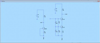
of a CCS in LTspice (a couple of possible circuitries are attached to this post. Component values are just tentative).
Output impedance measurement
In order to "isolate" the output impedance I have inserted an LTspice constant current source in place of the 100 ohms resistors in the two circuitries in the attachment. As far as I can see these current sources have a 10e17 output impedance and thus (much) higher than the circuitries' own impedances. This appears to work reasonably when doing an AC analysis ... I get some curves that show a rising tendency going up in frequency. However, it would be great if I was actually able to see what the output impedance is at the various frequencies? Anyone has some ideas for this?
Noise measurement
Also, in terms of noise (current sources removed and replaced with not 100R but 0.1R in the two circuitries) I get some somewhat odd values - several millivolts up to ~1kHz when I ask LTspice to measure noise at Iout2 and Iout3 ... I reckon my way of measuring is not correct - so I would much appreciate if one of you may suggest a reliable way of measuring this noise 🙂
Thanks & cheers,
Jesper
Hmmm ... I reckon this may have been discussed here so I hope you will bear with me if I address it again ...
As it is I am in need of measuring:
- the output impedance as a function of frequency, and
- the noise level - also as a function of frequency
of a CCS in LTspice (a couple of possible circuitries are attached to this post. Component values are just tentative).
Output impedance measurement
In order to "isolate" the output impedance I have inserted an LTspice constant current source in place of the 100 ohms resistors in the two circuitries in the attachment. As far as I can see these current sources have a 10e17 output impedance and thus (much) higher than the circuitries' own impedances. This appears to work reasonably when doing an AC analysis ... I get some curves that show a rising tendency going up in frequency. However, it would be great if I was actually able to see what the output impedance is at the various frequencies? Anyone has some ideas for this?
Noise measurement
Also, in terms of noise (current sources removed and replaced with not 100R but 0.1R in the two circuitries) I get some somewhat odd values - several millivolts up to ~1kHz when I ask LTspice to measure noise at Iout2 and Iout3 ... I reckon my way of measuring is not correct - so I would much appreciate if one of you may suggest a reliable way of measuring this noise 🙂
Thanks & cheers,
Jesper
Attachments
Can somebody tell me what is the needed resolution(timescale) in the simulation command editor to be able to read the right FFT for 1khz ?I used to have 1ms...10ms start-stop for 1khz and 10us max timestep.I modified it to lower values(0.1...1us) and the THD changed from -130db to -60...90db ...
Frans, the problem was easily solved, no problem. I was just wondering where it came from. Probably not the models as all active device come from outside LTspice. Maybe the cap or res models. Or maybe the routines that calculate the time step for the next iteration.
We'll probably never know.
Jan
In the program folder there is changelog.txt. Open it, do you see any lines that are relevant?
There is a black art to making simulations easier for the simulator which involves deep knowledge of how the solver works. For instance in the next version of VBIC, the excess phase network was changed from a passive network to a B-source cascade, and this improves convergence:
https://cache.freescale.com/files/technology_manufacturing/doc/MSM2003_BJT_COLIN_MCANDREW.pdf
I have not seen a really exhaustive writeup of the whys and hows.
As it is I am in need of measuring:
- the output impedance as a function of frequency, and
To directly plot the impedance of the second circuit you would right click on a trace name in the waveform viewer and enter this:
V(Iout2,Vneg)/Ic(Q1)
You will get a phase and magnitude plot. If you right click on the magnitude scale, you can change between Bode, Cartesian and Nyquist coordinates.
The stimulus source should modulate the input voltage. Note that the stimulus source can be anywhere that doesn't get between the voltages/currents being probed, as for a constant impedance V/I is the same regardless of the magnitude of V.
To see just the real part of the impedance you can use
re(V/I)
For the imaginary part you can use
im(V/I)
And the Bode equivalents are
mag(V/I)
ph(V/I)
All this and more can be found in the LTspice help file in the waveform viewer arithmetic section.
If you want to plot capacitance, you solve for capacitance in the capacitive reactance equation:
Xc = 1/(2piFC)
C = 1/(2piF*Xc)
Which in the waveform viewer would be entered as:
C = 1/(2*pi*freq*(V/I))
Where freq is the instantaneous frequency variable provided by the waveform viewer for just this purpose.
Same process works for inductance.
However, this results in a plot that treats resistance as if it were a capacitor with frequency-dependent capacitance (the same is true for some cheap capacitance meters). For this reason if the capacitance is smaller than the series resistance, the plot will be wrong. In order to get around this you can operate on just the imaginary part of the impedance using:
C = 1/(2*pi*freq*im(V/I))
This way it tells you the correct capacitance.
Note that all these plots are only showing capacitance when the line is horizontal, this means capacitance is constant with frequency. A capacitance that is not constant with frequency is not a capacitor, but something else.
Sorry, i just read Mooly's advices (Bob Cordel inspiration) about fft in the beginning of this topic , i put the exact numbers and now i get ideal numbers like anybody else...🙂 now i fully understand why the usual 10us timestep in a 5...10us interval is better 😉Can somebody tell me what is the needed resolution(timescale) in the simulation command editor to be able to read the right FFT for 1khz ?I used to have 1ms...10ms start-stop for 1khz and 10us max timestep.I modified it to lower values(0.1...1us) and the THD changed from -130db to -60...90db ...
- Home
- Design & Build
- Software Tools
- Installing and using LTspice IV (now including LTXVII), From beginner to advanced