I now found another glitch. I have trouble getting some circuits (but not all) containing ccs to work properly.
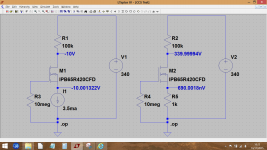
In teh circuit below, a rather simple LTP, I get the right op points in DC, but in transient, the AC signal at the plates is in the microvolts range. If I put a 1k resistor in parallel with the CCS, then the circuit works correctly. Any idea why?
In teh circuit below, a rather simple LTP, I get the right op points in DC, but in transient, the AC signal at the plates is in the microvolts range. If I put a 1k resistor in parallel with the CCS, then the circuit works correctly. Any idea why?
Attachments

No quick answer.
Although it sounds crazy, does it work OK if you try 100k ? or a 1meg or a 10meg across the CCS
Although it sounds crazy, does it work OK if you try 100k ? or a 1meg or a 10meg across the CCS
does it work OK if you try 100k ? or a 1meg or a 10meg across the CCS
No. The calculated gain is >30 from input to each output. Paralleling the ccs with 100k gives a gain of 0.1 and with 1M something like 0.01. The gain is basically what I would get with just the R and no ccs at all.
It runs just fine... GIGO, please check your tube model.
I use Kevin's model from the sticky thread in the tube section. Worked for me correctly in other circuits. But I'll try the Ayumi model and see what happens.
I just threw a CCS into a quick sim and it didn't behave as expected for me either. The current source actively 'pushes' its set current value into the circuit, in other words its fundamentally different to a 'current sink' as we know it.
The voltages in the right hand part of the first diagram are correct.
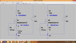
Try this and see if it works correctly.
The voltages in the right hand part of the first diagram are correct.
Try this and see if it works correctly.
Attachments

OK, found my error. I used node labels to label my 2 plate dc voltages, instead of text. I didn't realize that when you use the same node label in 2 places, it connects the 2 points electrically but you don't see it on the diagram. I had assumed the node labels are for user clarity only and the sim keeps its own node numbering system.
I just threw a CCS into a quick sim and it didn't behave as expected for me either. The current source actively 'pushes' its set current value into the circuit, in other words its fundamentally different to a 'current sink' as we know it.
Yes, this is exactly what I observed. I get circuit voltages into the giga and teravolts. I just can't figure out what the rules are because most of the time the ccs acts appropriately.
Edit: I don't know what it means and what it does when you check the "active load" box, but when I had ccs issues, it didn't work right with either setting.
Last edited:
 Mysteries like that can drive you crackers.
I just can't figure out what the rules are because most of the time the ccs acts appropriately.
I find an awful lot of knowledge is assumed when it comes LT. That has been my experience anyway.
Yes. In all fairness, if I had to use LTspice in my day job, I'm sure I would take a class first and then I'd have an LTspice guru on speed dial. Probably for a fee.
As a DIY proposition, with no formal training, it's actually pretty good. Ever try to learn CATIA by yourself at home?
As a DIY proposition, with no formal training, it's actually pretty good. Ever try to learn CATIA by yourself at home?
😀 CATIA, a lovely girl 🙂
(If I'm honest, well I've never even heard of it actually... OK so Google tells me more...)
(If I'm honest, well I've never even heard of it actually... OK so Google tells me more...)
Need to be carful with perfect devices. They will provide infinite current/voltage if required. And in both directions. A perfect CS will provide negative voltag in a circuit with no negative voltage sources if it has to to to keep the current constant. Add resistance to limit the voltage/current (right in the source). And some kind of clamp to the rails to prevent unrealistic over voltage or "negative" voltages. Maybe there's a way to do this in the model. It wod be very handy and I'ld be surprised if they haven't thought of this as it would be a common problem.
NT
Syntax: Ixxx n+ n- <current> [AC=<amplitude>] [load]
This circuit element sources a constant current between nodes n+ and n-. If the source is flagged as a load, the source is forced to be dissipative, that is, the current goes to zero if the voltage between nodes n+ and n- goes to zero or a negative value. The purpose of this option is to model a current load on a power supply that doesn't draw current if the output voltage is zero.
This load flag looks promising, would have to play with it to see exactly what it does.
Fair enough. I will install LTspice and look at user-friendliness and functionality. Thanks.
I've never used Multisim.
I suspect this is a case of what a person is used to and has taken the time to understand and figure out. Same goes for stuff like PCB software. Once you have a grip on one product you are going to prefer that over anything else simply because its familiar.
Need to be carful with perfect devices. They will provide infinite current/voltage if required.
Exactly.
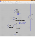
The perfect current source isn't really what we want in the tail of the LTP because it will force its set current back into the circuit. You only have to reduce the supply voltage to zero to see that the current source back feeds everything, developing a negative voltage. Change the 'active load' flag and it behaves as expected.
Attachments
I'm not a regular user of LTSpice, but when I tried the LTP circuit that dgta posted, it made no difference whether the Active Load is switched on or off, they both worked without issue.
Yes, it seems very circuit specific as to what happens.
I can't quite understand this if I'm honest because the current source in LT has in effect, an infinite open circuit voltage. So why does that sometimes work as expected in a circuit and sometimes not. If you place a 1ma current source into LT and slap a 1meg across it you get 1kV across the resistor. So although its a current source, its also a voltage generator when presented with a load.
I can't quite understand this if I'm honest because the current source in LT has in effect, an infinite open circuit voltage. So why does that sometimes work as expected in a circuit and sometimes not. If you place a 1ma current source into LT and slap a 1meg across it you get 1kV across the resistor. So although its a current source, its also a voltage generator when presented with a load.
Sure all curent sources produce voltage to drive the current thru the rest of the circuit. Just like a voltage source will produce current to keep the voltage constant across the circuit. The problem comes from perfect sources. Which will output infinite current/voltage in either polarity if needed to keep the current/voltage constant.
Sure all curent sources produce voltage to drive the current thru the rest of the circuit.
Yes... but... when you think of the real world LTP example and having a 'current source' in the tail, that current source would often be a single transistor, or a FET, both of which generate no intrinsic voltage of their own. If we simulate both those examples, they work as expected. More correctly, its a current sink in this example.
If you go through the Tube DIY thread, there are literally hundreds if not thousands of simulations that use the ideal current sources (instead of a discrete CCS, gyrator, etc.) and they all seem to work fine, so I am surprised that this problem has not been spotted much earlier.
- Home
- Design & Build
- Software Tools
- Installing and using LTspice IV (now including LTXVII), From beginner to advanced