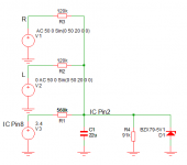
You got it wrong, the effective R is 120k paralleled with 120k and 91k =36k
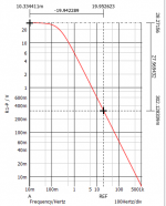
-3dB at 0.2Hz. when playing a 20Hz tone at 60V the level is 40dB down at 0.6V, this is well below you 2V trigger.
But when you have 2Hz, 6V will trigger your DC protection.
-3dB at 0.2Hz. when playing a 20Hz tone at 60V the level is 40dB down at 0.6V, this is well below you 2V trigger.
But when you have 2Hz, 6V will trigger your DC protection.
Last edited:
To H713
Even the impedance and design of speaker cables affects the distortion that occurs at the speaker terminals. This resistance is added to the resistance of the relay contacts. I studied many amplifier designs, as a rule, there are very bad slow and cheap relays everywhere, and only in unique amplifiers there are very good expensive multi-contact relays and several pieces in parallel on one channel. This is only done to reduce harmonic distortion and improve contact reliability and durability. There are also schemes for covering the main feedback of the contacts of these relays and even a scheme for covering the feedback of the resistance of the speaker cables. In the German reference book by P. Schrittek on sound circuitry, calculations are shown both with a load of 8 Ohm and a power of 200 W (the standard value of which is given by the manufacturers of amplifiers), the current through the load for comparison on an ordinary resistor reaches 7.1A, and for a real complex load in the form of speakers over 40A.
An amplifier with a capacitor capacity of 500,000 uF at 110V on rails clearly claims to be high-end and there is no much sense in talking about savings. I have also seen how in such amplifiers the developers put not only bad cheap relays but also very cheap speaker terminals and speaker cables inside the amplifier to save money. It looks ridiculous and as a result, such amplifiers sound, as a rule, with a mismatch with their price, and they also sell poorly. Consumers quickly find out which amplifier models are really successful and correctly made, without hack-work and saving on "matches".
I still do not see how series resistance with the output of the amplifier will result in harmonic distortion. It certainly affects the damping factor, but that is a different issue.
Some relays and speaker terminals use a ferrous material for the conductor, which has been shown to introduce some distortion. Is that what you're talking about?
Some relays and speaker terminals use a ferrous material for the conductor, which has been shown to introduce some distortion. Is that what you're talking about?
According to Ohm's law, a nonlinear current always causes a nonlinear voltage drop across the resistor through which this current flows. This is the real nonlinear signal distortion, which should not have been and will not be in the event that there is no such resistance. If this same resistor also has a nonlinear resistance, the overall picture will become even worse. The relay contacts have just such a resistance, it is nonlinear, especially if these contacts have oxide from operation under current and from time and old age. This applies to relays where there is no iron in the contacts. Iron-containing relays are even worse. Speaker connectors should also be free of iron and nickel, which is often applied before plating with gold in cheap connectors for economy and a beautiful shine. It is easy to check with a neodymium magnet. Good connectors do not react at all even to a powerful neodymium magnet.
You got it wrong, the effective R is 120k paralleled with 120k and 91k =36k
-3dB at 0.2Hz. when playing a 20Hz tone at 60V the level is 40dB down at 0.6V, this is well below you 2V trigger.
But when you have 2Hz, 6V will trigger your DC protection.
Still trying to understand this...
So, with 2 x 120k and 91 k resistors, I believe the thresholds are set at about 2Volts as per the datasheet calculations.
For this to work, it should resemble a highly exaggerated low pass filter, which basically raises pin 2 when dc or a very low frequency is detected (high frequencies should not trigger and hence need to be attenuated, which makes it a low pass filter).
The series resistors are 120k in parallel giving 60k. I do not understand the purpose of the 91k parallel to the capacitor from a filtering point of view. So to me, it looks like 60k in series with a capacitor. Therefore f = 1/(2.pi.R.C). So picking f as close to 0 (dc) say 2 Hz, should yield, C = 1(2. pi. 60000. 2), which is 1.32 uFarads.
Is that not the case ?
Thanks
Last edited:
Try to simulate it, not the IC, but just the cap and resistors.

Then I looked at the data sheet and saw that the positive and negative threshold are quite different, +620mV and -170mV, so with the 91k attenuator it would be +2V and -0.55V treshold.
Now a single resistor of 560k to the 3.4V ref voltage pin8 will center to +/- 1.47V.
The 22u is a good value.

I added the Zener so when there is some cathastrophic failure and the output voltage hangs on a rail the IC and cap don't get fried.
Also with the Zener you do not need a bipolar cap, a normal 10V Tantal 22u is perfect.

Then I looked at the data sheet and saw that the positive and negative threshold are quite different, +620mV and -170mV, so with the 91k attenuator it would be +2V and -0.55V treshold.
Now a single resistor of 560k to the 3.4V ref voltage pin8 will center to +/- 1.47V.
The 22u is a good value.

I added the Zener so when there is some cathastrophic failure and the output voltage hangs on a rail the IC and cap don't get fried.
Also with the Zener you do not need a bipolar cap, a normal 10V Tantal 22u is perfect.
Last edited: