cakyol, you have waded in to the deep end of the pool, and it seems like you need others to save you as all the technical decisions and assessments start to get harder and harder.
Which ever path you take, it will be ugly, as you want to use a level of filter capacitance that is way beyond that used by other designs that you can point to and clone.
Can I suggest you do some basic design preparation yourself using PSUD2 (as LTSpice may be a step too far for you). It can tell you the capacitor charge timing based on the effective resistance of the power transformer, and the changing current levels. You can then estimate power dissipation levels of a primary side resistor by the reflected secondary current. You can choose a resistor and estimate the temp rise based on the thermal resistance and what heatsinking you have available. You can then go through a few tradeoffs for different value limit resistors, and how long it will take to substantially charge your cap. Lots of fun before you even start to buy parts. Or you could buy some parts and see what happens if you feel confident enough.
Which ever path you take, it will be ugly, as you want to use a level of filter capacitance that is way beyond that used by other designs that you can point to and clone..
I think I mistype something in a previous post...
The capacitors that I use in another project are 33,000uF each rail (CGS333U100X8L)
The value that you are looking at for most concern in this application is the RIPPLE current.
These caps that I use are huge cans and can withstand ripple current up to 25A each!!!
I am sure that most every experienced person here would say that you have gone beyond usefulness if you exceeded the ripple by much more than 2x your rail current capacity. My rule of thumb is (since I use 2 caps in each rail now) is to have 2 caps, each ripple rating for the max current that I can supply to each rail.
They say you can't have sex in Red Square. Because the advice of passers-by will be very annoying.
The strongest and fastest speaker protection is provided by a transformer or autotransformer at the amplifier output, such as in McIntosh amplifiers. Also, a tapped transformer allows the high voltage on the rails to be matched to the optimum load resistance. This can reduce the distortion of the output stage by several times.
Such a transformer or autotransformer is also the most costly way of doing it. For a 500W amp, that's a seriously big transformer.
Is a 500W transformer a lot? An autotransformer with the same dimensions will be twice as powerful. Look at McIntosh, the dimensions of their autotransformers are exactly the same as those of a power transformer. But such protection is already on, it does not need time to operate. Also, the relay contacts have contact resistance and, consequently, signal distortion. The relay contacts can also stick, they may not break the electric arc at all. And in general, the very fact of an electric arc from a faulty amplifier to the speakers is not a very pleasant fact.
McIntosh MC2KW Power Amplifier Manual | HiFi Engine
McIntosh MC1.2KW Monoblock Power Amplifier Manual | HiFi Engine
McIntosh MC2KW Power Amplifier Manual | HiFi Engine
McIntosh MC1.2KW Monoblock Power Amplifier Manual | HiFi Engine
Last edited:
A 500W transformer or autotransformer at 20 Hz is considerable. I'm not saying it's impossible, but it is costly and not available off-the-shelf as far as I know. Furthermore, if given the option I would certainly choose to keep a very large piece of iron out of the signal path.
Amplifiers of this power level have used a traditional protection circuit for years. I've witnessed a few big amps blow up catastrophically, but a suitably large relay is usually just fine and is usually able to break the connection if configured properly.
Now as for the monster cap banks, there absolutely needs to be some form of rail fusing so as to avoid creating an explosion if the output stage fails. Those fuses do add some output impedance, however, and at that point one must question what the advantage of such large caps is.
What can be expensive in an autotransformer? The easiest winding. You can wind up even easier by using just one primary coil as an inductor and that's it. And even this will become an insurmountable obstacle in the path of direct current from the amplifier to the speaker in the event of an accident. But, unlike a relay, an autotransformer can optimally match the impedance of the speakers with the output stage and reduce the distortion of the output stage, for example, from 0.5% to 0.05%. The relay just can't do that. Conversely relays increase distortion.
Is a 500W transformer a lot? An autotransformer with the same dimensions will be twice as powerful. Look at McIntosh, the dimensions of their autotransformers are exactly the same as those of a power transformer. But such protection is already on, it does not need time to operate. Also, the relay contacts have contact resistance and, consequently, signal distortion. The relay contacts can also stick, they may not break the electric arc at all. And in general, the very fact of an electric arc from a faulty amplifier to the speakers is not a very pleasant fact.
McIntosh MC2KW Power Amplifier Manual | HiFi Engine
McIntosh MC1.2KW Monoblock Power Amplifier Manual | HiFi Engine
That is why I was going to use a Mosfet relay (Rod Elliott's P198 project). I have mosfets that are at 2.5 milliohms when fully on, which is almost as good as a series copper wire.
I do admit using a transformer would be ok for protection but I doubt I can pick such a txformer off the shelf at a reasonable cost which will operate seamlessy between 20 -> 20 khz. They must be very specially wound with very special cores. Besides, I do not have the space for them unfortunately.
What can be expensive in an autotransformer? The easiest winding. You can wind up even easier by using just one primary coil as an inductor and that's it. And even this will become an insurmountable obstacle in the path of direct current from the amplifier to the speaker in the event of an accident. But, unlike a relay, an autotransformer can optimally match the impedance of the speakers with the output stage and reduce the distortion of the output stage, for example, from 0.5% to 0.05%. The relay just can't do that. Conversely relays increase distortion.
I doubt it is that easy. The core will saturate differently at different frequencies, changing the transfer function with frequency. Since it is NOT like a power txformer at 50/60 hz whose waveform you do not care about, since it will be rectified anyway, audio output must be absolutely precise otherwise terrible distortion will result.
Last edited:
I also have another question on 1237 based protectors.
Pin 2, which detects the DC offset, have wildly varying capacitor values based on different designs, altho most of the other components are pretty similar.
What should that value ideally be ?
In my estimate, if it is too large, it seems like it will trigger prematurely at lower frequencies. So, to allow a 10 Hz signal to go thru without firing, what should the approximate value be ?
I have seen values ranging from 22uF all the way to 68uF.
Has anyone actually experimented with it ?
Thanks
I and not only I made toroidal output transformers. There are no problems at all. The video shows a unique studio power amplifier GOTHAM PFB-150WA, manufactured in the USA in 1957 with an output toroidal transformer. Designed for cutting master varnish disks in the production of phonograph records. GOTHAM PFB-150WA Power Amplifier - YouTubeI doubt it is that easy. The core will saturate differently at different frequencies, changing the transfer function with frequency. Since it is NOT like a power txformer at 50/60 hz whose waveform you do not care about, since it will be rectified anyway, audio output must be absolutely precise otherwise terrible distortion will result.
I think it's time to get rid of relays and fuses in amplifiers. Now a lot of unique fast-acting protective devices have appeared in the power industry for these purposes, suitable for amplifiers.
Last edited:
Any time I can remove a big transformer which is very much non-ideal from the signal path, I like to do so. Getting perfect linearity out of magnetics is difficult.
There's a few reasons to want to avoid them here.
1) There is no reason why the OP shouldn't be able to design a 500W amp with extremely low THD without an impedance matching transformer. It's been done many, many times. MC2, QSC and many others have gotten extremely good performance without the use of such transformers.
2) Good relays (or FETs, like the OP is using) will not have an appreciable impact on distortion.
3) Not all of us live in a transformer winding shop. Yes, I've designed and wound custom transformers. That said, it is NOT my first choice. It is a considerable project, even if it is an "easy" transformer to wind. It's also somewhat costly.
4) It takes up considerable chassis space and adds considerable weight. I suspect it would make for a VERY deep 3U chassis if done.
5) Traditional protection circuits work pretty well. Instant? No, but they're fast enough.
Cakyol, the value of that cap will be chosen by the RC time constant, where f = 1/(2piRC)
Nanocrystalline alloys with extremely linear hysteresis loops and record low losses have now appeared. Moreover, even on the simplest electrical steel M6, as in McIntosh transformers, you are guaranteed to get a transformer with extremely low harmonic distortion, since the nonlinearity of the hysteresis loop is not at all included in the transfer function of the transformer. The main thing is to provide a high inductance of the primary winding and a low leakage inductance between the windings, which is not a problem at all in an autotransformer.
Computer simulations of a push-pull output stage with transistors included in a common collector circuit show that any increase in load resistance always leads to a significant reduction in distortion of this stage. This is what the McIntosh autotransformer does, besides protecting the speaker.
The relays have a contact resistance of the order of 0.1 ohm minimum for a new relay. After a while, this resistance will be much higher. With a load current of only 1 A, this will already lead to an increase in distortion above 0.1 V only at this resistance, which is quite a lot for a high-end amplifier. Аt a current of 10A, the amount of distortion only due to the presence of a relay will reach over 1V!And this is already an unacceptable value even for a cheap amplifier.
Last edited:
The relays have a contact resistance of the order of 0.1 ohm minimum for a new relay. After a while, this resistance will be much higher. With a load current of only 1 A, this will already lead to an increase in distortion above 0.1 V only at this resistance, which is quite a lot for a high-end amplifier. Аt a current of 10A, the amount of distortion only due to the presence of a relay will reach over 1V!And this is already an unacceptable value even for a cheap amplifier.
I have yet to measure this actually occurring in a real amplifier. I recently did a rebuild on an MC650 from 1998 that blew and output module. That amplifier has seen extensive use since it was manufactured. Upon testing the speaker relay, it had no issues. While working on that amplifier, I took the time to fix and test about four extra MC650 modules that had failed in other amps (hint, there's a 5532 on the input board that likes to die if severely overdriven). All of these modules are at least 20 years old, and none of them showed any issues in this regard.
Maybe if the contacts get really bad it will cause measurable distortion, but so long as the signal does not pass through the soft iron in in the relay, distortion seems to remain reasonably immeasurable. I haven't had the time to characterize contact resistance to determine how linear it is, but series resistance with the output of an amplifier != distortion. Only if that resistance is non-linear will there be a distortion increase, assuming the load is reasonably linear.
With all of that said, semiconductor technology has come a very long way over the last 20 years, and the use of a solid-state switch is a much better solution from a reliability standpoint. Although we often get away with it, having to break the high DC current when an output device fails is a lot to ask of a relay.
Now as for the autoformers...
If you want people to take this idea seriously, it needs to be a viable option. As of right now, I am not aware of any commercially available autotransformer that will work for this application. Perhaps there is a boutique manufacturer, and perhaps one could have a transformer winding company manufacture some. Either of these options is extremely costly in most cases, probably $300+ for a stereo amplifier in the 100W range, at least in the country I live in.
I am also not aware of too many places where a person can buy suitable transformer cores in small quantity for a reasonable price. Most of us are not interested in placing an order for 50+ cores. Most people would also prefer to avoid spending $100 and a bunch of time on a protection circuit. Yes, it does reduce distortion into lower impedance loads. But it's also possible to get low distortion into 2-ohm loads without such a device.
I have seen values ranging from 22uF all the way to 68uF.
do not look at the cap values alone but the resistor associated with it and the time constants it makes..
I mentioned this in post #135, but it might have been buried. The RC time constant is what counts. The cutoff frequency is given by f_c = 1/(2piRC). Knowing this you can size the values of R and C such that it will only trigger the protection circuit at frequencies below 10 Hz or whatever you choose. Do keep in mind, however, that while you could configure it to pass a 1 Hz sine wave without triggering the protect circuit, there is Zero reason for it to pass anything below 20 Hz, and the protection circuit needs to be fast enough to avoid damaging the woofers of whatever speaker is connected when the amp fails. Speakers really don't like DC, so a fast protection circuit is a good thing.
Also, the cap needs to be a bipolar electrolytic. This is very important, since an amp can go DC to either rail.
Also, the cap needs to be a bipolar electrolytic. This is very important, since an amp can go DC to either rail.
Last edited:
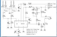
So, in the schematic below, Ra, Rb & Rc are calculated so that the DC voltage threshold is about +/- 2 volts. So, is the frequency of trigger given by:
1/ (2 x pi x 120,000 x (C1) 22u), which translates to 0.06 hertz ?
Unless I made the calculations wrong, this is too close to danger. I would rather have it 4 or 5 hertz.
So for 5 Hz, the cap value C1 should be 0.265 uF. Does that sound right ?
1/ (2 x pi x 120,000 x (C1) 22u), which translates to 0.06 hertz ?
Unless I made the calculations wrong, this is too close to danger. I would rather have it 4 or 5 hertz.
So for 5 Hz, the cap value C1 should be 0.265 uF. Does that sound right ?
Attachments
Last edited:
- Home
- Amplifiers
- Power Supplies
- inrush current limiting on the SECONDARY of a transformer