Hmmm . . . still no comments about my earlier concern about low frequency rolloff when a 1uf cap is combined with a 10k pot turned to the 12:00 position feeding an amp with a 10k input impedance?
Here's the comment again, for your convenience:
Here's the comment again, for your convenience:
Given all the technical expertise on this forum I would think that someone would comment. If my take on this is totally out to lunch, I'd like to know and understand why.But, if the unattenuated signal makes a major contribution to the "color", then keeping the volume control on the output would be better.
As I see it, the biggest problem with that is the parts values used in the original circuit. A 10k pot only measures 10k to ground if the pot is wide open, which is not a normal scenario.
I don't have any 10k volume pots but I just measured a 100k attenuator. Like most volume controls, it is an audio taper, which allows for more precise volume adjustment. When turned to maximum the resistance to ground is 100k, of course. But when set to 12:00 the resistance to ground is only 6.4k. So if the taper was the same, a 10k pot would measure ~640 ohms at 12:00.
As others have pointed out, the resistance of the pot on the output is in parallel with the input impedance of the amp and the combined resistance value is used to determine the -3db rolloff point with a high pass filter calculator. So the -3db point varies depending on the position of the pot.
A resistance of 640 ohms in parallel with 10k is ~600 ohms. When combined with a 1uf coupling cap a high pass calculator shows the -3db rolloff point is 265 Hz. And if the volume control is any set lower than 12:00 the -3db point is even higher.
As I see it, this is biggest problem with the original design if we assume that the "color" aspect is a desirable trait. But changing the value of the cap and pot is easy enough.
With a 100k pot (set to 12:00) and a 3.3uf cap the rolloff point would be ~12 Hz, assuming use with a SS or Class D amp whose input impedance is 10k.
If I'm misinterpreting something here, someone please correct me.

I seem to recall that Nelson Pass designed a circuit (with no tubes, of course) that allows the user to dial in varying amounts of 2nd order distortion to taste. I believe it might even be for sale in kit form on this site somewhere?A friend of mine who tinkers a LOT with Nelson Pass amplifiers (which sound superb) still admits that his go-to reference is his PP 2a3 amp.
The ECC82 preamplifier was my very first tube build, many years ago. I know what I am talking about. Tried all sorts of circuits including SRPP and mu-follower. I ended-up with the SRPP because it was the one with lower distortion for my application. It sounded best with both SS and tube amp. What would be your conclusion? Maybe it was by chance and I am the one who doesn't understand what was/is doing then?So you have built, tested and listened to this pre-amp using that "best spot"? If not, I'll probably defer to the person who has.
Anyway, I said an different thing.
If one likes introducing distortion instead of fixing the problem (better SS power amp or else) it's fine but please do not say that SS amps sound sterile and that's why people use tube power amps because it is not true. If a SS amp sounds sterile then that specific amplifier is crap or there are bigger issues elsewhere. The amplifier is the strong link in the audio chain for sure, tube or SS. They only have different behaviour and have different requirements.
And I was not joking about using a tube screamer....dirty and quick. This is no insult because introducing distortion on purpose is not HiFi, so everything is allowed.
Last edited:
The 3dB low frequency corner does not change that much with shaft rotation. Attached is the plot of how that corner frequency changes with shaft rotation for several different output capacitor values. The "orange" line is for the 1.0µf capacitor shown on the schematic. The first plot is for the 10kΩ load you mentioned. The second one is for a 100kΩ load for reference.Hmmm . . . still no comments about my earlier concern about low frequency rolloff when a 1uf cap is combined with a 10k pot turned to the 12:00 position feeding an amp with a 10k input impedance?
Hopefully these will answer your question.
Attachments

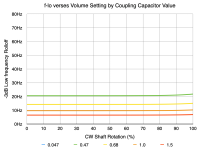
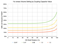
Thanks for posting those. Any idea why my results show something very different?The 3dB low frequency corner does not change that much with shaft rotation. Attached is the plot of how that corner frequency changes with shaft rotation for several different output capacitor values. The "orange" line is for the 1.0µf capacitor shown on the schematic. The first plot is for the 10kΩ load you mentioned. The second one is for a 100kΩ load for reference.
Hopefully these will answer your question.
I just used a couple of standard online calculators. The first calculates resistors in parallel. If the audio taper rate of the 10k pot is the same as my 100k, then at 50% the resistance to ground would be ~640 ohms. Put that in parallel with the 10k load of the amp and the result is 601 ohms.
When that 600 ohm resistance is combined with a 1uf cap using a high pass calculator the -3db point is 256 Hz not 10 Hz.
According to the calculator, if the resistance is 601 ohms it would take a 26uf cap to achieve a -3db point of 10Hz.
Even if the pot was turned wide open, measuring 10k to ground, the resulting resistance in parallel with the 10k on the amp input would be 5k. And combined with the 1uf cap the -3db point would still not be 10Hz, it would be just under 32 Hz according to the calculator.
Is there some major flaw in my approach? Am I using the wrong calculators or values? Or ????


You need to include the source impedance (i.e. the output impedance of the cathode follower) in your calculation. My plots assume the cathode follower has an intrinsic output impedance of 6500Ω. Just represent the cathode follower as a thevenin equivalent with a 6500Ω impedance and then calculate the voltage transfer function.
It seems you discovered the secret of the average tube magic on the dark side of HiFi. "Just do something". It may surprise you but many don't calculate at all and do empirical designing.Thanks for posting those. Any idea why my results show something very different?
I just used a couple of standard online calculators. The first calculates resistors in parallel. If the audio taper rate of the 10k pot is the same as my 100k, then at 50% the resistance to ground would be ~640 ohms. Put that in parallel with the 10k load of the amp and the result is 601 ohms.
When that 600 ohm resistance is combined with a 1uf cap using a high pass calculator the -3db point is 256 Hz not 10 Hz.
According to the calculator, if the resistance is 601 ohms it would take a 26uf cap to achieve a -3db point of 10Hz.
Even if the pot was turned wide open, measuring 10k to ground, the resulting resistance in parallel with the 10k on the amp input would be 5k. And combined with the 1uf cap the -3db point would still not be 10Hz, it would be just under 32 Hz according to the calculator.
Is there some major flaw in my approach? Am I using the wrong calculators or values? Or ????
View attachment 1166370View attachment 1166373View attachment 1166374View attachment 1166375
Can't say I've ever heard the term thevenin equivalent but I would have guessed that the output impedance of a cathode follower would be much lower than 6.5k.You need to include the source impedance (i.e. the output impedance of the cathode follower) in your calculation. My plots assume the cathode follower has an intrinsic output impedance of 6500Ω. Just represent the cathode follower as a thevenin equivalent with a 6500Ω impedance and then calculate the voltage transfer function.
I've read many posts that mention output impedances of various cathode followers and I don't recall any of them being over 1k and typically they are considerably lower. I would have suspected that 650 ohms would be more likely.
Are you saying that the 6.5k output impedance of the CF should also be parallel with the value of the pot when set at 50% and the 10k input impedance of the amp even though there is a 1uf cap that separates the 6.5k from the others?
If so the calculator indicates that the parallel resistance of the three is 550 ohms. And combined with the 1uf cap, the -3db point is even higher at 289 Hz.
If that's not correct, how do you determine the resistance value that should be entered into the high pass calculator?
According to the calculator, with a 1uf cap the resistance would need to be 15.9k in order for the -3db point to be 10Hz.
It seems to me that the cap, followed by a resistance to ground would form a high pass regardless of what is going on prior to the cap.
If the resistance varies, the rolloff point also varies and, unlike your graph, which indicates that the rolloff point is essentially flat during most of the pot's rotation. And as the resistance to ground increases (as happens when the pot is turned up to 100%) the -3db rolloff point goes down. Your graph indicates that it goes up.
Again, I'm just trying to understand what's going on and how to calculate the result.


I'm also unclear about what my concern with frequency rolloff has to do with "voltage transfer function". I'm not even sure what that is.
You are correct, I grabbed the wrong sheet and didn't check. The actual output impedance of the cathode follower is 648Ω||11kΩ ≈ 612Ω. I've attached the appropriate plot.
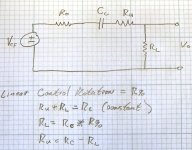
However it is important to remember that the control portion above the wiper appears in series with the loading capacitor. The circuit looks like the one attached. In this diagram, Ro represents the total output impedance of the cathode follower (612Ω in this case). Ru represents the portion of the volume control above the wiper contact point. Rl represents the portion of the volume control below the wiper contact point. This is why the lower 3dB point climbs at major control rotation because the series resistance is decreasing. Remember that this is the lower 3dB point being calculated.
The situation is further complicated due to the fact that the control variation is logarithmic with respect to control shaft position. At the 50% (or 12:00 o'clock) position with a 10kΩ control, Ru ≈ 9000Ω and Rl ≈ 1000Ω. This needs to be taken into account when solving for the voltage transfer function Vo/Vcf.
Does this clear it up?
B.t.w... I avoid on-line calculators whenever possible. It's impossible to see under the hood so I prefer to perform calculations by hand (or my own spreadsheet).
Attachments
When we talk about "rolloff" what we are addressing is the voltage transfer function as a function of frequency. In essence this is simply the ratio of the voltage at the circuit "output" to the voltage at the circuit "input". Literally Vout/Vin. If the circuit between the input and output is purely resistive, then the voltage ratio is "fixed" and is independant of frequency. If the circuit contains frequency dependent elements (i.e. capacitors and/or inductors) then, in general, the voltage ratio is dependent on frequency.I'm also unclear about what my concern with frequency rolloff has to do with "voltage transfer function". I'm not even sure what that is.
Any coupling circuit can be reduced to what is called a "two port" circuit (i.e. one with an "input" port and an "output" port). The characteristics of such a circuit are fully described by the impedance seen at each port and the voltage transfer functions between the ports. See this articel for further information: https://en.wikipedia.org/wiki/Two-port_network
No, I'm still confused . . . you still have a 1uf cap in series with the signal and your pot measures 1k to ground.However it is important to remember that the control portion above the wiper appears in series with the loading capacitor. The circuit looks like the one attached. In this diagram, Ro represents the total output impedance of the cathode follower (612Ω in this case). Ru represents the portion of the volume control above the wiper contact point. Rl represents the portion of the volume control below the wiper contact point. This is why the lower 3dB point climbs at major control rotation because the series resistance is decreasing. Remember that this is the lower 3dB point being calculated.
The situation is further complicated due to the fact that the control variation is logarithmic with respect to control shaft position. At the 50% (or 12:00 o'clock) position with a 10kΩ control, Ru ≈ 9000Ω and Rl ≈ 1000Ω. This needs to be taken into account when solving for the voltage transfer function Vo/Vcf.
Does this clear it up?
The 1k to ground is in parallel with the 10k input impedance of the amp. So the resulting resistance is 909 ohms. And the high pass filter shows that the combination of a 1uf cap and 909 ohm R to have a -3db point of 175 Hz.


Why would the series resistance of the CF (6.5k) or the series resistance of the pot (9k) or the combination of the two (15.5k) change the rolloff frequency? The resistance value that's used to calculate high pass goes to ground, it's not in series with the signal.
And why would the rolloff frequency rise instead of drop when the value of Rl is increased, as your graph shows? The high pass filter indicates that it should drop as the resistance to ground increases, as it does when the pot is turned towards full volume output.
My concern was the rolloff frequency but you keep talking about voltage transfer function. I'm guessing that the formula you mention (Vo/Vcf), when translated into plain English, is just an engineer's way of describing the percentage of the signal that's being sent from preamp to the amp. Obviously, the higher the setting of the pot the more signal voltage is being sent to the amp.
OK, I see you just posted about that. I'll have to read the link tomorrow.
You say that since there is a cap in the mix that the "voltage ratio is dependent on frequency". But the high pass seems to be saying just the opposite - that the frequency (roll off point and, therefore the range) is dependent on the voltage ratio (presumably the % of the input signal which is sent to the amp), which is determined by the position of the pot. It indicates that as the resistance to ground (Rl) increases the rolloff point drops.
In effect, you seem to be saying that since there is resistance in series with the signal that the combination of a cap in series and a resistance to ground no longer functions as a high pass filter.
Last edited:
You are being confused by multiple points.
First, the plot I provided was NOT a plot of rolloff with frequency, but a plot of the -3dB point as a function of volume control shaft position.
Second, you cannot just ignore impedances in the signal path when analyzing a circuit. The output impedance of the cathode follower is in series with the capacitor as is the upper portion of the volume control. You have to account for ALL of those impedances when calculating the frequency dependent rolloff.
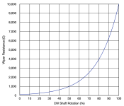
Third, the transfer function (i.e. output/input rolloff) as a function of frequency is dependent on the voltage control setting. The series capacitor does still function as a low frequency pole forming a "high pass" filter, but the circuit is more complicated than just a capacitor and a resistor to ground. And the volume control is non-linear. (see attached plot)
The -3dB point is dependent on ALL the impedances in the path. In this case the resistances in series with the capacitor (i.e. the CF output impedance AND the portion of the volume control above the control wiper), the portion of the control below the wiper tied to ground, and the input impedance of the downstream amplifier which is in parallel with the lower portion of the volume control. When calculating a voltage at a node in the circuit, you must account for ALL impedances between the voltage source and the node and those between the node and ground.
First, the plot I provided was NOT a plot of rolloff with frequency, but a plot of the -3dB point as a function of volume control shaft position.
Second, you cannot just ignore impedances in the signal path when analyzing a circuit. The output impedance of the cathode follower is in series with the capacitor as is the upper portion of the volume control. You have to account for ALL of those impedances when calculating the frequency dependent rolloff.
Third, the transfer function (i.e. output/input rolloff) as a function of frequency is dependent on the voltage control setting. The series capacitor does still function as a low frequency pole forming a "high pass" filter, but the circuit is more complicated than just a capacitor and a resistor to ground. And the volume control is non-linear. (see attached plot)
The -3dB point is dependent on ALL the impedances in the path. In this case the resistances in series with the capacitor (i.e. the CF output impedance AND the portion of the volume control above the control wiper), the portion of the control below the wiper tied to ground, and the input impedance of the downstream amplifier which is in parallel with the lower portion of the volume control. When calculating a voltage at a node in the circuit, you must account for ALL impedances between the voltage source and the node and those between the node and ground.
Attachments
Brilliant thread - I’m glad you posted it!I also want to apologize to Matt, I should have just emailed him this question instead of posting this here for people to attack his design, without even understanding what the goal is.
Another consideration ( I forgot before)
If the value of pot on output is too small, in addition of the limited Ft at low frequency the CF will change the working point changing the position of volume and increasing the Thd when it is in the worst condition ( at 50% of pot value, so -6dB less or more)
In conclusiont the "issue" are two not one.
Walter
There's a common idea that crossover distortion problems in (conventional, cold biased) semi-con amplifiers can be "fixed" or maybe mitigated by adding a different type of distortion in some magic profile of harmonic progressions, music of the spheres. Nobody ever explains how this could even work, but it's surprisingly well accepted. Personally, never found it to be the case.
All good fortune,
Chris
All good fortune,
Chris
Definitely INPUT volume control
because
- almost all input sources has huge p-p output level of signal.
and pot will be always working in lowering signal
- Less distortion of the preamplifing device because it will never reach the max level due to the power amplifier has lower input p-p signal for the max power...
.
Case:
Source say 3Vp-p + preamp Gain=10X => that is 30Vp-p to the power amplifier input...
So it is much better to have attenuation right after the source...
.
Value of POT is critical becuse I spot that almost every tuve design has too big value of pot say 100K at the input.
In the lover levels the "bigger side of pot" acting as the grid stopper and creatihng HF filter with Dynamic capacitances.
.
POT=1 / (2 PI Fo Cdyn)
Where Fo cut of -3db frequency, but for -0.25db @ 20KHz -3db is @ 131KHz...
Cdyn = Cgk + ( (abs(-A)+1) x Cga) ) where A=gain of the tube stage in X times, -sign is for pointing that stage is turning the phase for 180deg...
.
for interelectrode capacitances refer to this article
https://tubes.njunis.net/?p=311&lang=en
.
cheers
That is more a problem for cheap class AB (or should I say class B?) stuff and class D amps. For cheap mass produced amplifiers I don't think there is any urgency as only a fool might have high expectations. For class D amps it depends as there are some rather expensive ones. I personally do not care much as I have never used one, cheap or expensive.There's a common idea that crossover distortion problems in (conventional, cold biased) semi-con amplifiers can be "fixed" or maybe mitigated by adding a different type of distortion in some magic profile of harmonic progressions, music of the spheres. Nobody ever explains how this could even work, but it's surprisingly well accepted. Personally, never found it to be the case.
All good fortune,
Chris
A proper class AB amp or class A do not have any problem. The Eamlab Studio 162, that I recently had for some time, is rated 90W into 8R, 160R into 4R, 250W into 2R and works in class A up to 10W for 8R load. So it's class A where it matters most, even with 4R load. At a street price of 1.4K euros is not cheap but it is affordable.
Last edited:
Today one can buy cheap and reliable mass produced stuff that sounds real good. Some exceed expectations which is nice. The opposite happens more often.
I think Chris means that some try to “solve” semiconductor amplifiers crossover distortion (does that still exist in the wild!?) by adding other distortion in the form of tube preamps. This thought defect is noticed by others as well.
I think Chris means that some try to “solve” semiconductor amplifiers crossover distortion (does that still exist in the wild!?) by adding other distortion in the form of tube preamps. This thought defect is noticed by others as well.
Last edited:
- Home
- Amplifiers
- Tubes / Valves
- Input or Output Pre-amp Volume Control