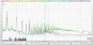
Here is the comparison measurements to put it into context. This is with a DAC connected directly to the input of the 211, but not playing anything and a measurement across the output terminals of 1 channel with the speaker in place doing it's thing zzz ing and hummming a bit.
Green trace is at 3/4 volume on the Pot (very high perceived zzzzz, and a bit more hummmm)
Red Trace is at full volume on the Pot (acceptable noise)
Blue trace is a zero volume on the Pot (lowest noise)
My logic is if the cables connected to the pot were picking up interference then why would they not show this on full volume, so I suspect the potentiometer in close proximity to the interstage transformer; however I have spoken to the original amplifier builder and he said interstage transformers would not be the problem, and has no other ideas.
I also measure the resistance from the pot mounting to the signal ground and it's still 100R so it's not creating another earth loop of sorts in this way.The 211 has a lifted 100R circuit ground from chassis earth
I may try taking the amplifier off the shelf and move the pot away from the transformer dangling but I have been told not to waste my time as it's not that?
What else could it be?
🙁
Attachments
@tonescout: looking at your power amp schematic from post #14 it seems you power amp already has a 100K volume control. It also has a 100K resistor in series with it. YOu could safely raise this to 330K which should attenuate the input by another 10dB.
Cheers
Ian
Cheers
Ian
This is a schematic of the Kondo Ongaku, not mine - I just used the diagram as an example of a pot on the input at 100k. I don't know my schematic unfortunately.@tonescout: looking at your power amp schematic from post #14 it seems you power amp already has a 100K volume control. It also has a 100K resistor in series with it. YOu could safely raise this to 330K which should attenuate the input by another 10dB.
Cheers
Ian
I just tired moving the potentiometer out of the location it was screwed into; and it made no difference. It was dangling in the air so also not connected to the chassis earth at its mounting point - just the same. So I assume this removes the too near the transformer theory.
Weird 🙄
Weird 🙄
The reason you do not get the ZZZZZ with the pot turned up full is because the amp is now loaded with the output impedance of the preamp which is about 1K so it is much less susceptible to pickup. Did you try screening the leads to and from the pot?
Cheers
Ian
Cheers
Ian
Great idea - I had discounted on the basis that when at full volume there was no zzzz. I will try it - Thanks!!!The reason you do not get the ZZZZZ with the pot turned up full is because the amp is now loaded with the output impedance of the preamp which is about 1K so it is much less susceptible to pickup. Did you try screening the leads to and from the pot?
Cheers
Ian
Can I ask a question related to this without trying to hijack?
What is the input impedance of the following:
Input to 10k MN taper balance pot feeding 100k log volume pot.
What is the input impedance of the following:
Input to 10k MN taper balance pot feeding 100k log volume pot.
oh - it does the same on a 50R Dac, but maybe the same mechanism applies, I will try and see - just need to get some screen braidThe reason you do not get the ZZZZZ with the pot turned up full is because the amp is now loaded with the output impedance of the preamp which is about 1K so it is much less susceptible to pickup. Did you try screening the leads to and from the pot?
Cheers
Ian
Assuming the infinite impedance after the volume pot - 9.09k at the central balance position and above for each channel, increasing to 10k at channel's max fade outWhat is the input impedance of the following:
Input to 10k MN taper balance pot feeding 100k log volume pot.
Just get some regular screened cable. The length you need is very short so it will make little difference which one you get.oh - it does the same on a 50R Dac, but maybe the same mechanism applies, I will try and see - just need to get some screen braid
Cheers
Ian
That's what I thought. Thanks 🙂Assuming the infinite impedance after the volume pot - 9.09k at the central balance position and above for each channel, increasing to 10k at channel's max fade out
Thanks for the suggestion but I actually found some screened braid I had for something else so will use this it will prevent a lot of desoldering, and cleaning 🙂Just get some regular screened cable. The length you need is very short so it will make little difference which one you get.
Cheers
Ian
Surprisingly (to me) I found using the cheapish pot and the twisted duelund on full volume sounded better than the original short run of cable and the 100k wire-wound resistor > go figure!
Interesting you have a 100K wirewound resistor across the input. Not a good idea in my view. Not necessary from the noise point of view and a 100K wirewound needs many turns of wire which turns it into a pretty good aerial. Might be an idea to replace it with a 100K metal film.Thanks for the suggestion but I actually found some screened braid I had for something else so will use this it will prevent a lot of desoldering, and cleaning 🙂
Surprisingly (to me) I found using the cheapish pot and the twisted duelund on full volume sounded better than the original short run of cable and the 100k wire-wound resistor > go figure!
Cheers
ian
Sorry for not being clear the 100K wirewound was originally run from signal to ground to act as the input impedance, and was taken out to be replaced by the pot, so at full volume on the pot it's kind of acting exactly the same, and with a lot of additional cable I would have guessed a high quality wirewound vs a cheap plastic/carbon track pot and a lot more cable. (I think the stuff I removed was solid core slive/ptfe) would have sounded similar but if anything worse, but its actually a lot nicer.Interesting you have a 100K wirewound resistor across the input. Not a good idea in my view. Not necessary from the noise point of view and a 100K wirewound needs many turns of wire which turns it into a pretty good aerial. Might be an idea to replace it with a 100K metal film.
Cheers
ian
Just shows you that exotic components don't really make a difference. Design and implementation count for much more.Sorry for not being clear the 100K wirewound was originally run from signal to ground to act as the input impedance, and was taken out to be replaced by the pot, so at full volume on the pot it's kind of acting exactly the same, and with a lot of additional cable I would have guessed a high quality wirewound vs a cheap plastic/carbon track pot and a lot more cable. (I think the stuff I removed was solid core slive/ptfe) would have sounded similar but if anything worse, but its actually a lot nicer.
Cheers
Ian
Well - I tried shielding the twisted cable from the pot to the board, but unfortunately no difference.....shame :-(
Interesting. Sounds like you might have a grounding problem. Can you tell me at what point the 0V is connected to the chassis? Also is mains earth connected directly to the chassis?Well - I tried shielding the twisted cable from the pot to the board, but unfortunately no difference.....shame :-(
Cheers
Ian
211 has mains earth to the chassis, and 100R lift to the circuit ground in the 211. Remember the only change is to swap the previous 100K fixed resistor for a 100K mono pot on each channel. See post 42, so not sure why changing the pot changes the ground position.
I will however try some alternatives on what is connected to earth and see //
I will however try some alternatives on what is connected to earth and see //
Interesting. Sounds like you might have a grounding problem. Can you tell me at what point the 0V is connected to the chassis? Also is mains earth connected directly to the chassis?
Cheers
Ian
OK, but what I was looking for is where exactly is the chassis connected to circuit ground. Is it as the power supply, the input or somewhere else?211 has mains earth to the chassis, and 100R lift to the circuit ground in the 211. Remember the only change is to swap the previous 100K fixed resistor for a 100K mono pot on each channel. See post 42, so not sure why changing the pot changes the ground position.
I will however try some alternatives on what is connected to earth and see //
A schematic of the 211 would nbe useful too if you have one.
Cheers
Ian
- Home
- Amplifiers
- Tubes / Valves
- input impedance and potentiometer