Might be too much.
100k pot has the output impedance of 25k at most (middle position), so something in the 220-270k range is enough.
Depends on the amp, of course.
1M is common practice. The idea is to preserve the stock input impedance of 100k when the pot is turned full tilt when used as a pure power amp if he ever uses a lower gain preamp. So a 100K parallel with 1M is 90K Ω but a 100K parallel with 220K is 68K. And 1M is high or innocuous enough not to affect the stable impedance much at any position. It is just there really for safety in the case of pot failure so the grid wouldn't go berserk without a ground reference.
Well, we still don't know what the input tube is and how it's implemented. Some high gm ones might not feel well with the 1M in case of pot failure.
True, more often than not it won't cause any problems, I'm just playing on the safe side here.
True, more often than not it won't cause any problems, I'm just playing on the safe side here.
Some high gm ones might not feel well with the 1M in case of pot failure.
You do have a point. Since he posted an Ongaku schematic I was just assuming common audio tubes like 12AY7 or 12AX7 which is perfectly comfortable with a 1M grid leak resistor. The OP should answer what is the input tube in his power amp before proceeding.
There's nothing wrong with adding a potentiometer to the input of a tube power amplifier. Purists be damnned! Many vintage models did that all the time, including all the McIntosh models.
You can always add a high value grid leak resistor (1M or higher) to ground to ensure the grid is referenced to ground in case pot's wiper contact fails intermittently to avoid scratchy noise. That's a pretty common practic in many amps.
Too much system gain and no way to attenuate it is frustrating and the sound can be overly sensitive which tends to be nervous or jumpy sounding. What good is preserving signal path purity if you are using the poorest range of the preamp pot? Just add a 100K pot and 1M grid leak resistor and be done with it.
Another advantage of a pot in front of a power amp is that now you have the ability to use line source equipment direct in and compare to using with a preamp, an AB test, so you can hear how the preamp influence the sound or how neutral or not the preamp is. You may or may not like it but at least now you know.
yes......
Well, we still don't know what the input tube is and how it's implemented. Some high gm ones might not feel well with the 1M in case of pot failure.
True, more often than not it won't cause any problems, I'm just playing on the safe side here.
high gm tubes require low values of grid leak resistors, new prod kt88 want 100k, and the QE08-200 wants lower ....
You do have a point. Since he posted an Ongaku schematic I was just assuming common audio tubes like 12AY7 or 12AX7 which is perfectly comfortable with a 1M grid leak resistor. The OP should answer what is the input tube in his power amp before proceeding.
The circuit I am not sure of, other than it has 12Watts output and has a 6C45 input valve and a Lundahl interstage transformer feeding the 211. Voltage on 211 measures about 1000V
I have measured the inputs from line level equipment's. Never saw any values over 1 volt P-P. input bias on say a 12ax7 in the range of 1.5 volts. I tend to bias my 12ax7(s) right at 1 volt dc. other tubes like 12au7, bias is in the range of 3.0 volts, so no need to "play safe" with one of those....... :/
...... and still awaiting to see any drawing of any "hi-fi" circuit using safety bias, although I am sure all of that will be changing in the near future........
my build not only have volume control after the first gain stage, but it's two inputs, the low level input from headphone jack, and high level line input, are so much electrically isolated in the first gain stage, I even throw away the input selector switch.
is part of my design goals, not to build equipment's that already exist, but to build equipment's that can demonstrate better ways to do things..... like throwing away the input selector switch............using fixed bias upper and lower on an SRPP, using a para-feed drive for a 5 watt laptop console amplifier, using a choke loaded tail for a PI, and such.......
That's exactly why I was cautious.The circuit I am not sure of, other than it has 12Watts output and has a 6C45 input valve
6C45P allows for the grid leak resistor of 150k max.
I personally would probably skip the pot idea and go with just the constant resistor in series with the input.
That's exactly why I was cautious.
6C45P allows for the grid leak resistor of 150k max.
I personally would probably skip the pot idea and go with just the constant resistor in series with the input.
Yeah this is easier to test too I can just out a resistor in series with the signal on the interconnect and try it 🙂 then think about a more permanent solution.
what would be a sensible starting value - 3K6, 4K7 I have to hand to try?
You can wire some random 50-200k potentiometer as the rheostat (connect the wiper to one of the leads), connect it in series with the input, find the needed position, then measure it's resistance and substitute it with the constant resistor of the closest standard value.
Leo Fender did not make separate Preamps and Power Amps like we are talking here but integrated units.
Leo Fender dod not make Hi Fi equipment like we are talking here.
You are barking at the WRONG tree.
Save your "personal opinions" and "pet ideas" for the Musical Instruments section of the Forum.
Leo Fender dod not make Hi Fi equipment like we are talking here.
You are barking at the WRONG tree.
Save your "personal opinions" and "pet ideas" for the Musical Instruments section of the Forum.
my build not only have...
is part of my design goals, not to build equipment's that already exist, but to build equipment's that can demonstrate better ways to do things.....
Apparently, you are making this thread about yourself. "My build," "my design goals," my this, my that, blah, blah, blah. You haven't contributed a single thing to help the OP. We get it, you are smarter than everybody else. Wouldn't it be better off you start your own thread so you can leave us alone in the peanut gallery?
So a bit more thinking and some questions on the logic of input impedance.
If a 100K pot is put across the input in a conventional manner like this https://hfc-fs.s3-eu-west-1.amazonaws.com/s3fs-public/tkd_2cp25_datasheet_0.pdf
with top of pot connecting to input signal, bottom to ground/common and wiper to signal out. Then is the input impedance the sum of the resistance in the signal path and the resistance to (ie the whole pot 100K) or does is change according to the attenuation.
The reason I am asking is related to my set up where I have a fixed 100k to ground from the signal-in on the power amp (211 valve amp) and I want to add a 50K pot in before this (because I have one to try). I have 2 options as I see it, just take a part of the pot as a variable resistor and don't take the bottom of the pot to earth (option B in my sketch) and to take the pot to ground, effectively making the bottom of the pot in parallel with the 100k (option A).
So my question really is what is the input impedance in each case A and B.
Is A = Rx+Ry in parallel with 100k, and B Rx + 100k.
Probably really dumb questions but I think I am about to learn something!!
Thanks,
Attachments
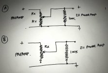
For case A, the input impedance at the maximum level setting of the 50k pot is 50k // 100k = 33k.
The Zin approaches 50k for larger attenuation settings, and there is an infinite range of attenuation.
For case B, the Zin varies from 100k at the maximum level setting to 150k at the minimum level.
The range of attenuation of the 50k pot is very limited, only about -3.5dB.
Only use case A.
The Zin approaches 50k for larger attenuation settings, and there is an infinite range of attenuation.
For case B, the Zin varies from 100k at the maximum level setting to 150k at the minimum level.
The range of attenuation of the 50k pot is very limited, only about -3.5dB.
Only use case A.
Last edited:
you know what, i repaired a Realistic 6V6 SE amp, the main volume control looked like B...worked fine...
yes, and yes....i actually liked B, my reasoning is that the grid leak is fixed to 100k, plus loading the preamp is better in the case of B, because in A there is a 50k loading, in B 200k...
just be mindful of the noise....
So my question really is what is the input impedance in each case A and B.
Is A = Rx+Ry in parallel with 100k, and B Rx + 100k.
yes, and yes....i actually liked B, my reasoning is that the grid leak is fixed to 100k, plus loading the preamp is better in the case of B, because in A there is a 50k loading, in B 200k...
just be mindful of the noise....
Last edited:
Hey thanks everyone for some clear thinking 🙂
I have this 50K pot, and I can of course connect it in mode A and mode B. What I guess I will find out if I try them both is the influence of input impedance AND attenuation on the sound.
It all sounds good as it is now BUT the volume wheel on the SP8 preamp is a little bunched and sensitive. My friend who has an ARC SP10 and a Yoshiba 50 power amp with an included volume pot says he really likes the ability to play with the influence of how the pre and power amps contribute to the sound character to get to a good 'balance' should it sound more 'ARC' or 'Yosh'.......interesting concept I guess, I've never thought of it like this before.
I use this website to determine how much gain loss I will experience when playing with the pot, so agreed with case B I am pretty limited, just not sure yet if 3.5 dB is enough (probably not!)
50-Step Shunt Attenuator Resistor Calculator - Neville Roberts
Last edited:
pots input resistors
Hello,
I'm not really worthy of this thread but, when I was gearing up to put a post phase inverter master volume into my newly built 20 watt Marshall Plexi, I was tediously warned to do things in a certain way to avoid potential catastrophy.
One, was to use potentiometers manfactured by PEC (precision electronic corp or something) and that to also install 1 Meg resistors across particular pot tabs in the case that the wiper was to ever lift, or, if the negative bias was to ever disappear. I had to take this as the presence of a high ohm grid leak was a very prudent idea even if you paid 30 bucks for a very robust potentiometer, since this pot was both dividing the incoming signal voltage and carrying the bias voltage to the grids.
Best,
Phil
Last edited:
- Home
- Amplifiers
- Tubes / Valves
- input impedance and potentiometer