Output valves can fail catastrophically if they lose bias; resistor loaded valves are safe enough.
There are two other issues that might matter in some cases. First, if the pot is carrying DC current (like some bias setups do) a shunting resistor will pull DC current through the wiper contacts. This degrades the contacts and becomes a potential issue itself. The circuit must be designed so that failure of the wiping contact causes less rather than more, idle current in the biased stage.
Second, for signal AC through a pot's wiping contacts, distortion caused by the contacts will vary with signal current, and hence with loading. Does a 1M Ohm resistor consume enough signal current at line level (the original discussion) to contribute significant distortion to a clean, quality pot? Seems unlikely to me, but a good excuse to keep the pot clean.
All good fortune,
Chris
Gents,
Thanks for the feedback, I took my time focusing on other activities outside the 211 - mainly due to the physical effort of moving the amplifier off it's shelf with its ridiculous weight, and various covid restrictions on having anybody come in and help move it with me.
My friend also has a potentiometer on his power amplifier, and has been persuading me of the benefits this has in matching a high gain pre-amp. So I thought why not, as I had a perfect location on the amp to fit this in aesthetically and conveniently. I put in 2 x 100K pots, but no grid leak resistor yet, as I was confused on the advice on the size it should be with my 6c45 Pi input valve.
So the question is related to a ZZZZZ at relatively high frequency that I now have when using the pot turned down (not on full volume, where it is not evident).
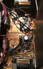
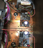
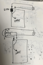
I can't see why this would happen, unless it's the annoyingly close proximity to the interstage transformers, and stray fields to the new 100k mono pots see images that hopefully are clear, attached showing the before and after, with a circuit layout. I removed the original 100K to ground and this could work as the location for the grid leak resistor.
Any ideas?
Thanks for the feedback, I took my time focusing on other activities outside the 211 - mainly due to the physical effort of moving the amplifier off it's shelf with its ridiculous weight, and various covid restrictions on having anybody come in and help move it with me.
My friend also has a potentiometer on his power amplifier, and has been persuading me of the benefits this has in matching a high gain pre-amp. So I thought why not, as I had a perfect location on the amp to fit this in aesthetically and conveniently. I put in 2 x 100K pots, but no grid leak resistor yet, as I was confused on the advice on the size it should be with my 6c45 Pi input valve.
So the question is related to a ZZZZZ at relatively high frequency that I now have when using the pot turned down (not on full volume, where it is not evident).
I can't see why this would happen, unless it's the annoyingly close proximity to the interstage transformers, and stray fields to the new 100k mono pots see images that hopefully are clear, attached showing the before and after, with a circuit layout. I removed the original 100K to ground and this could work as the location for the grid leak resistor.
Any ideas?
Attachments
I've found that adding a pot to the input of a power amp can cause oscillation at mid pot settings (in my case caused by RF/SMPS noise). Running shielded wire instead of twisted helped dramatically.
There's also the input attenuator from Harrison Labs... This will give a more consistant result.
https://www.hlabs.com/products/attenuators/
I suggest you set the pot where you want the level, measure it, and replace it with a 2 resistor voltage divider at the input (the opposite end from the RCA jack).
1 volt P-P or just Peak? Isn't line level specified as 2V RMS?I have measured the inputs from line level equipment's. Never saw any values over 1 volt P-P. input bias on say a 12ax7 in the range of 1.5 volts. I tend to bias my 12ax7(s) right at 1 volt dc. other tubes like 12au7, bias is in the range of 3.0 volts, so no need to "play safe" with one of those.
This is interesting news regarding the Max 150k - also shown hereThat's exactly why I was cautious.
6C45P allows for the grid leak resistor of 150k max.
I personally would probably skip the pot idea and go with just the constant resistor in series with the input.
I guess this means running a 1M to earth from output signal on the pot no longer makes any useful sense?
That depends on what you call "line". I have line amps that put out 10 volts. That said, I calibrate my meters to 0VU = 1.228V RMS (3.46V peak to peak).1 volt P-P or just Peak? Isn't line level specified as 2V RMS?
Well, you still want the constant resistor of some sort in this place.I guess this means running a 1M to earth from output signal on the pot no longer makes any useful sense?
Like I said earlier, 220-270k is high enough for not loading the pot output too much under normal operational conditions, and at the same time low enough to keep the 6C45P more or less sane should the pot wiper fail.
What I do get confused about is the effective input impedance of a potentiometer in the classic format I have used during its use over a range of positions. Just measuring DC resistance to earth of course it remains at 100K, but how does this correlate to input impedance?Well, you still want the constant resistor of some sort in this place.
Like I said earlier, 220-270k is high enough for not loading the pot output too much under normal operational conditions, and at the same time low enough to keep the 6C45P more or less sane should the pot wiper fail.
In the classic format where the pot slider is connected directly to the grid, the input impedance is equal to the value of the pot. This is because the grid is effectively open circuit.What I do get confused about is the effective input impedance of a potentiometer in the classic format I have used during its use over a range of positions. Just measuring DC resistance to earth of course it remains at 100K, but how does this correlate to input impedance?
Cheers
Ian
so the series element of the pot + the shunt left to earth together always = 100K, irrespective of the position of the slider?In the classic format where the pot slider is connected directly to the grid, the input impedance is equal to the value of the pot. This is because the grid is effectively open circuit.
Cheers
Ian
Nope.so the series element of the pot + the shunt left to earth together always = 100K, irrespective of the position of the slider?
100k at zero volume, 100k||Rshunt at max volume.
going to have to plead stupidity on this - no idea what this means ...sorry!!Nope.
100k at zero volume, 100k||Rshunt at max volume.
But, if you read my post carefully you will see I said for the classic case where the wiper is connected directly to the grid (i.e. there is no shunt resistance because the grid to ground impedance is effectively infinite) then the pot impedance is always 100K. As soon as you add a shunt resistor from the grid to ground then you have to account for it.Nope.
100k at zero volume, 100k||Rshunt at max volume.
I am puzzled why this is a problem for anyone. Even the 6C45P will allow a maximum of 150K grid to ground. So connect a 150K from grid to ground and use a 10K pot. Input impedance will then vary from about 9.3K to 10K.
Cheers
Ian
You mean the two parts of the pot track. The top-to-wiper part is the series resistor,so the series element of the pot + the shunt left to earth together always = 100K, irrespective of the position of the slider?
and the wiper-to-ground part is the shunt resistor. Then regardless of the wiper position,
the series plus shunt sum remains at 100k, which is the input impedance.
If we neglect the tube's input capacitance, then the 100k resistance is the input impedance.
However, including the tube capacitance, the input impedance is not just resistive.
It becomes a complex impedance, which varies with the wiper position and forms a low pass filter.
The lowest frequency of the filter corresponds with the 50k+ 50k (-6dB) wiper position.
But if the tube capacitance is small enough, it can be neglected for audio purposes.
Last edited:
I've read your post carefully indeed and I'm not contradicting you in any way. Just making some clarification for a general case with shunt resistor of finite value.But, if you read my post carefully you will see I said for the classic case where the wiper is connected directly to the grid
"||" means "in parallel". R1||R2=R1*R2/(R1+R2).no idea what this means
100k||270k=73k, for example.
The output resistance of a pot is 1/4 its resistance at -6dB attenuation.
If the pot is a 100k pot, and if it's a linear taper pot, when you put the control at 12 o'clock, or 50k ohms from top pin to wiper and 50k ohms at bottom pin to wiper, the output resistance of the 100k ohm pot will be 25k ohms.
If you have a 1Meg resistor from grid to ground (and the wiper of the pot is also going to the grid of the following stage) then that 1M resistor will be in parallel with the 100k pot resistance from input to ground, so 1M*100k/1M+100k = 90.9k from grid to ground.
However, there will also be series resistance introduced by the pot (the voltage divider that reduces the level going to the following stage grid).
If you have a 12AX7 after the pot, with its Cin of about 100pF to 200pF, this could become important for frequency response at different positions of your volume control. Worst case,
25k series with 200pF parallel = HF roll-off of -3dB at 31.8kHz (which is awfully close to the audio band).
It's a system, and every alteration to that system has consequences both desired and undesired. Good system design takes all these interactions into account.
Don'cha hate when that happens?
It is indeed system. The maximum output impedance of a pot being 25% of its value is true only if the driving source impedance is zero. Of course in most cases these days it is well below 1K. So if we are considering the system we have to ask why use a 100K pot, why not use 10K because it sure helps with first stage Miller issues.
If you do choose a sensibly low pot values then you are much more likely to get Miller problems in the second stage. If you have a 12AX7 first stage driving another 12AX7 then the source impedance driving the second stage is likely to be 50K or more.
Cheers
Ian
If you do choose a sensibly low pot values then you are much more likely to get Miller problems in the second stage. If you have a 12AX7 first stage driving another 12AX7 then the source impedance driving the second stage is likely to be 50K or more.
Cheers
Ian
ThanksIt is indeed system. The maximum output impedance of a pot being 25% of its value is true only if the driving source impedance is zero. Of course in most cases these days it is well below 1K. So if we are considering the system we have to ask why use a 100K pot, why not use 10K because it sure helps with first stage Miller issues.
If you do choose a sensibly low pot values then you are much more likely to get Miller problems in the second stage. If you have a 12AX7 first stage driving another 12AX7 then the source impedance driving the second stage is likely to be 50K or more.
Cheers
Ian
I am driving the 211 with an old ARC SP8, and I may end up not using the line-stage if i can't reduce the hum; as currently with zzzzz the pot fed direct from a DAC it is not actually significantly different sounding to be honest, i prefer the Sp8 sound (but it hums) and the direct is different and slightly less preferable but it ZZZZZZs. Of course it both zzz and hmmmmm if I use both volume pots together......yawn!
- Home
- Amplifiers
- Tubes / Valves
- input impedance and potentiometer