That is the way to do it.Perhaps I should practice on some SMD build I dont care about, to get good at it?
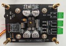
About the V1.5 board: the guys at Shenzen Pillor are not consequent with the heatsinks as the blue ones used to be mounted on the P version. The input connector relocated is OK but the 3.5 mm input does not make matters better. Shitty and unreliable connector and no unbalanced/bal conversion circuit. From the picture it seems ceramic caps are 25V rated which would be a pity.
The output connectors are Phoenix knockoffs but they're a more practical solution than the push connectors. I had to fit 6.3 mm spade connectors on the old version of the board for practical use but the PCB holes/pads were there which was good. Spade connectors may appear clunky, they are simply good. All together the connectors are placed better for practical encasing of the amplifier board.
Setting the SMPS to a higher output voltage and adding a 5V LDO may be a good improvement.
All in all this board looks like one of the better implementations of the chip in the "affordable class" (Chi-Fi is a word verboten by the woke brigades). Add an unbal/bal conversion circuit to it, short the input caps and use film caps on the unbalanced/bal circuit (complete with volume control) and the BRZHiFi and A8 will be forgotten. If they would add a PSU on the board it would be the MA12070 version of Icepower 50ASX2 😀
Last edited:

I did a listening of the board at LF and A8 at HF.
The board sounds good but a little raw more like TPA32xx.
But A8 is nice on top.
When I switched to A8 at LF it was clear muddier in MF also the board noiser at HF with some EMI in left channel
but I don't have it in any case yet and close to my monitor so not optimal.
@jean-paul any unbal/bal conversion circuit you have in mind?
And what to short?
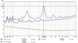
If it's because the board getting warmer and "played in" or that I had to measure and redo my EQ settings but
now it sounds realy good!
Had an strong peak at 53hz and a big dip between 100-200hz.
Had my son to listen, who are not dealing with my interest but I have him to listen to all my amps and speakers.
This is sick!
What an spacey sound!
😊
now it sounds realy good!
Had an strong peak at 53hz and a big dip between 100-200hz.
Had my son to listen, who are not dealing with my interest but I have him to listen to all my amps and speakers.
This is sick!
What an spacey sound!
😊
This is good song which I feel the difference between my TPA3255 and MA12070.
The basdrum hangs a little bit more on MA not just die.
Patrcia Barber-Regular Pleasures
Good reference song.
The basdrum hangs a little bit more on MA not just die.
Patrcia Barber-Regular Pleasures
Good reference song.
Solve, like many if not most class D ICs the chip has balanced inputs but in this price class unbalanced sources are normal. Also many simply don’t like balanced setups.
However, the chip does not perform optimally noise/hiss wise when grounding one of each channels input pins via a capacitor to GND. Unbal/bal conversion gives better results when using it in an unbalanced setup like with volume control and then converted to balanced going to the board.
However, the chip does not perform optimally noise/hiss wise when grounding one of each channels input pins via a capacitor to GND. Unbal/bal conversion gives better results when using it in an unbalanced setup like with volume control and then converted to balanced going to the board.
Last edited:
Trying to follow this rather long thread..
Is this board still a valid and good choice? In the beginning of the thread some seem to like it a lot.
I'm thinking of getting 2 of them. One board for stereo mains and one for subwoofer duty. with a miniDsp doing Crossover and EQ.
https://www.audiophonics.fr/en/ampl...lifier-module-ma12070-160w-4-ohm-p-14732.html
Or are there better options?
For diy, IMHO there's no better option at that price point available. I'd have ordered this board first until I tried to save some money with the BRZhifi stuff - what I regret in hindsight.Trying to follow this rather long thread..
Is this board still a valid and good choice? In the beginning of the thread some seem to like it a lot.
I'm thinking of getting 2 of them. One board for stereo mains and one for subwoofer duty. with a miniDsp doing Crossover and EQ.
https://www.audiophonics.fr/en/ampl...lifier-module-ma12070-160w-4-ohm-p-14732.html
Or are there better options?
I connected the second board to tweeters and used the JST connector with pre mounted 20cm cables and soldered on an
RCA cable but pretty noisy.
So I soldered direct to board with both L+R earth to center ground.
Much better so skip that JST connector.
Did an dirty quick test with mic to tweeter.
RCA cable but pretty noisy.
So I soldered direct to board with both L+R earth to center ground.
Much better so skip that JST connector.
Did an dirty quick test with mic to tweeter.
Attachments
Just pulled the trigger on 2 of these.
I was recommended to use 2 of these for Power: Meanwell LRS-350-24. So will properly try that.
There are also these however double the money.. are they twice as good? https://www.audiophonics.fr/en/smps...-dalimentation-decoupage-300w-24v-p-6196.html
Going to be fun to test these and see if they are up to the task 🙂
/JZ
Is this still a good option for unbalanced/rca inputs? Any better alternatives?For diy, IMHO there's no better option at that price point available. I'd have ordered this board first until I tried to save some money with the BRZhifi stuff - what I regret in hindsight.
I am using the BRZHIFI unit, with basic modifications as suggested by theAnonymous1, driving a pair of Focal monitors in a nearfield setup and it is still excellent sounding after a month. I'd like to try the more expensive board, but feel no need at this point. Looking forward to future Infineon merus entries.
So I have had some Fusion 10 Pures (version 1 with 12" SEOS) for a long time as my primary HT L-R channels and I always had a hunch I screwed up the XOs when I built them ~a decade ago but I never knew what I wanted to do to make them just a little bit better until I got some JBL 308P MK2 s in ~2018.
I was driving them off of a Sony STR-DN1060 until it developed transformer hum. Anyway, now I have decided digital XO (DBX Driverack PA2) and bi-amp. For this, I think I might leverage the PA3s (one per speaker) and this sweet little infineon chip. There is also the DIY PILLOR board with blue/red heatsinks to consider, but the PA3s has two chips which makes my brain wonder what config they used. They spec it like a single chip device, but the ASR tests showed it to be only about a 50% gain over a single chip device. I have a hunch it is just two paralleled BTL configs but I am left wondering.... why? I read the whole thread and I recall @theAnonymous1 doing a little project with power modes.
I also see that nobody has, as of yet, actually photographed the PA3s PCB and shared it beyond the Audiophonics images. There was some griping earlier in the thread about needing an MCU to set modes, but it seems Topping delivered here. Since it is a simple microswitch button to swap between BAL/SE in addition to power... this can only be done with an MCU.

The MCU:

- Looks like maybe a dual op-amp right behind vol pot to 'switch' between SE/BAL? If the opamp is driven by 5V then 1.9-2Vpp seems possible. Symmetrical layout of SMD components to either side would suggest a unity gain phase splitter design. But I feel two channels would require a second dual opamp. Maybe on the bottom? My EE is a little weak.
I really wish somebody would take one of these apart and take some photos. Maybe I will have to take the plunge and order a couple. Can anybody explain to me (like I am five) why a paralleled BTL would be better than dual mono PBTL?
If you made it this far, I am sorry.
I was driving them off of a Sony STR-DN1060 until it developed transformer hum. Anyway, now I have decided digital XO (DBX Driverack PA2) and bi-amp. For this, I think I might leverage the PA3s (one per speaker) and this sweet little infineon chip. There is also the DIY PILLOR board with blue/red heatsinks to consider, but the PA3s has two chips which makes my brain wonder what config they used. They spec it like a single chip device, but the ASR tests showed it to be only about a 50% gain over a single chip device. I have a hunch it is just two paralleled BTL configs but I am left wondering.... why? I read the whole thread and I recall @theAnonymous1 doing a little project with power modes.
I also see that nobody has, as of yet, actually photographed the PA3s PCB and shared it beyond the Audiophonics images. There was some griping earlier in the thread about needing an MCU to set modes, but it seems Topping delivered here. Since it is a simple microswitch button to swap between BAL/SE in addition to power... this can only be done with an MCU.
The MCU:
- Seems to be a 20-pin (T)SSOP package.
- We know that the 102700 chip speaks I2S.
- We know that, for example a PIC programmer uses a 6-pin programming interface.
- We know that default power mode is PMode 0, and best THD+N is PMODE1 and PMode2. All three are specified by Infineon as a filterless capable.
- There are two pin headers on the PCB. a 4-Pin and a 6-PIN. PIC controllers happen to require,,, wait for it,,, a 6-pin programming interface.
- Seems the likely candidates are PIC16F from Microchip/ATMEL, C8051 from SI Labs, NXP S08 maybe but unlikely due to cost (4-10x higher than others), perhaps STM STM8S30F10, perhaps Renesas R5F11?
- Voltage appears to be shared with the 12070 which means it's a 5V MCU.
- Looks like maybe a dual op-amp right behind vol pot to 'switch' between SE/BAL? If the opamp is driven by 5V then 1.9-2Vpp seems possible. Symmetrical layout of SMD components to either side would suggest a unity gain phase splitter design. But I feel two channels would require a second dual opamp. Maybe on the bottom? My EE is a little weak.
I really wish somebody would take one of these apart and take some photos. Maybe I will have to take the plunge and order a couple. Can anybody explain to me (like I am five) why a paralleled BTL would be better than dual mono PBTL?
If you made it this far, I am sorry.
Some photos for your consideration. I know @jean-paul wanted to see the output filtering.
'filters':


chip layout:

opamp:

MCU:

Thoughts:
'filters':
chip layout:
opamp:
MCU:
Thoughts:
- Thermal pads are a really really really poor thermal interface. The heatsink also almost no tension on it. Contact points are anodized. I would hesitate to say the heatsink is doing much at all.
- The ferrites in this are waaaaaay smaller than anything Infineon recommends.
- The Omron relays control the SE/BAL input. Relays are actually quite nice. Omron G6K-2P-Y-DC12. Unsure how to feel about itsy-bitsy relays in the signal path.
- Very tempting to mill an opening in the case for the heatsink.
Hi, thank you! I would not worry too much about heat. Still it would make sense to improve contact of the heatsink to the chips. It should don't need an opening in the casing?! I have yet to see an overheating chip. Don't worry about the relays, they are good quality.
Output filtering is absolutely inadequate which really is a pity. I will skip this one for that reason. Apparently an OPA1656 was worth the price but they avoided the costs of a few ferrite beads.
Output filtering is absolutely inadequate which really is a pity. I will skip this one for that reason. Apparently an OPA1656 was worth the price but they avoided the costs of a few ferrite beads.
Really great to hear about the relays. I still think I will short to BAL since these amps will live on the back of my 2-way speakers. Just less potential headache in a static setup; and easily reversible if I choose.Hi, thank you! I would not worry too much about heat. Still it would make sense to improve contact of the heatsink to the chips. It should don't need an opening in the casing?! I have yet to see an overheating chip. Don't worry about the relays, they are good quality.
Output filtering is absolutely inadequate which really is a pity. I will skip this one for that reason. Apparently an OPA1656 was worth the price but they avoided the costs of a few ferrite beads.
Yeah. I don't think the MA12070 really makes much heat at all but Topping put a massive heatsink on there so may as well use it. The other motive is I can then countersink in some screws to fasten the amps directly to the cabs and integrate them better. No holes on the board so naked running is out of the question.
It;s funny because the beads are there; they're just ridiculously tiny. If the massively oversized heatsink were milled away for clearance it would probably be quite simple simple to add them. There's space enough;. and I am betting the vast majority of purchasers are not making hacky active monitors using these amps.
No relay is of course better when you will use them balanced (maybe the opamp can go too). If you worry about the heatsink and still wish optimal heat transfer you could glue the heatsink with good thermal glue. Make sure to degrease the surface carefully. No way to remove them but I do this all the time and no regret. If such an amplifier would have a defective chip one will replace the whole amplifier I guess. It seems the heatsink is more optical/esthetical "make up" as everyone expects a heatsink. Motto: "the larger the better". If they would ask us we probably would prefer a small heatsink and the ferrite beads instead. The chip stays lukewarm at moderate volume levels anyway. If it would be my amplifier I would use 2 adequate smaller heatsinks and glue those.
You could check if you can cut/interrupt the output tracks somewhere to add ferrite beads and 2 x 1 nF. BTW you can replace those 4 x 100 µF 25V electrolytic input caps for 4 x 4.7 µF (or 10 µF) Wima 5 mm film caps. Pretin the lead wires and bend them with a pliers beforehand to fit to the PCB pads.
You could check if you can cut/interrupt the output tracks somewhere to add ferrite beads and 2 x 1 nF. BTW you can replace those 4 x 100 µF 25V electrolytic input caps for 4 x 4.7 µF (or 10 µF) Wima 5 mm film caps. Pretin the lead wires and bend them with a pliers beforehand to fit to the PCB pads.
Last edited:
If the output inductance is so small, why even use ferrite - with its magnetizing parasitic effect? Why not go air-core at ferrite bead levels of inductance value?
Actually I don;t think those are filters at all. I got out my little teslong borescope because it has a light and a short focal length.


I think those are diodes? They match the marking with OnSemi NSR0[12][FL]30NXT5G and size matches as well. They are .3mm wide and .6mm long.

Each piece is consistent in being |D_ where _ is M or E which OnSemi says would be month code.
Each center tap of RCA goes through a diode, and each speaker output has a diode.
The back of the board has tons of room for a filter if the case is able to be ditched. It certainly does look like it is set up in PBTL mode already. 0 continuity between R+ and any pins other than the two from that single chip.

The corresponding positive output vias can be seen between the chip and the SMD components just past the chipamp contacts. This is the L+ output.

1/4" TRS connectors: (Clone of CUI Devices SJ-63063B)
https://www.mouser.com/datasheet/2/221/Kobiconn_KC-300157-1173979.pdf
Mapped to relays and potentiometer:
LR = Left channel, Ring. (L-)
LT = Left channel, Tip. (L+)
RR = Right channel, Ring. (R-)
RT = Right channel, Tip. (R+)
Spacers are to chassis ground which is tied to SMPS negative. Pot has fully shared ground. TRS tip switch is tied directly to tip.
connections are A<->A, B<->B, C<->C, D<->D

PBTL super confirmed:

The surrounding components are taller than the amp chips. The heatsink contact is on the same plane as the surround and the relief cuts are perilously close to not clearing the components. I am guessing the heatsink was attached as more of a "we said we did it" because if it were fully torqued, there may be smoke. Note how the thermal pads are barely compressed. These pads are a bit cheap/crap and if the heatsink gets warm at all it is because the chips are waaaaay hotter.
I think those are diodes? They match the marking with OnSemi NSR0[12][FL]30NXT5G and size matches as well. They are .3mm wide and .6mm long.
Each piece is consistent in being |D_ where _ is M or E which OnSemi says would be month code.
Each center tap of RCA goes through a diode, and each speaker output has a diode.
The back of the board has tons of room for a filter if the case is able to be ditched. It certainly does look like it is set up in PBTL mode already. 0 continuity between R+ and any pins other than the two from that single chip.
The corresponding positive output vias can be seen between the chip and the SMD components just past the chipamp contacts. This is the L+ output.
1/4" TRS connectors: (Clone of CUI Devices SJ-63063B)
https://www.mouser.com/datasheet/2/221/Kobiconn_KC-300157-1173979.pdf
Mapped to relays and potentiometer:
LR = Left channel, Ring. (L-)
LT = Left channel, Tip. (L+)
RR = Right channel, Ring. (R-)
RT = Right channel, Tip. (R+)
Spacers are to chassis ground which is tied to SMPS negative. Pot has fully shared ground. TRS tip switch is tied directly to tip.
connections are A<->A, B<->B, C<->C, D<->D
PBTL super confirmed:
The surrounding components are taller than the amp chips. The heatsink contact is on the same plane as the surround and the relief cuts are perilously close to not clearing the components. I am guessing the heatsink was attached as more of a "we said we did it" because if it were fully torqued, there may be smoke. Note how the thermal pads are barely compressed. These pads are a bit cheap/crap and if the heatsink gets warm at all it is because the chips are waaaaay hotter.
- Home
- Amplifiers
- Class D
- Infineon MA12070 Class D