BRZ don't have the bottom as A8 even with that expensive linear 19v trafo I bought to my Allo Volt+.What about the difference between an unmodified BRZHiFi and the unmodified A8?!
I run A8 with LRS-24-350 Mean Well at 23.8V...
I have switched between TPA3255 and A8 as LF and HF and TPA ofcourse have more bottom with 48v
but I prefer MA12070 it's right for my speakers and room.
Another edit:
With BRZ at top the 3D sound meets, didn't feel that with A8 at top with TPA3255.
Last edited:

Cant you have both?😆Better to be addicted to cheap amps than to booze or drugs! 🙂
Yes they are.Interesting! Does the nanoDigi provide the clock for the 2 khadas boards so they’re in sync?
Very good clock.
They are build on ADAU1466 also with trafos on output so no strange ground loops.
But they stopped the production of it as they say component lach.
The new miniDSP Flex I think is even better.

Sometimes I wish the designers of these things would think for a moment about how someone might want to use it in a way other than just as-is out of the box.those nano bastards...
There's a capacitor on my HiFiBerry AMP2 I'd like to intercept, but they made it the size of all the other "bastards" and I dare not touch it, let alone hope to somehow get anything a little bit better in its place, without ruining the whole thing with just a glance from my soldering iron.
Thanks, whoever considered that particular cap as just another reference schematic BOM part placement on the board...
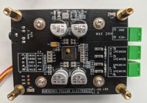
If you use 2 soldering tools you can lift the resistor. A bit like eating Chinese food with sticks western style 🙂 The resistor will stick to one of either so quickly clean the tip to which it sticks to a wet sponge. Now take a stainless steel tweezers and solder it to the right place. If unsure that the resistor survived and/or still is reliable a new one can be soldered. Easy peasy. I notice a trend that resistors on cheap boards "loose" their metal end part at one side even after short heating so my habit is to place a new one.I got two of this board today but it's version 1.5 without dip switches.
Those two resistors, R6, R9, measure 10k.
So if I want to run PBTL I have to move one of those nano bastards...
The layout has improved except the possibility to solder 2 x 1 nF film caps after the output ferrite beads. This was easy on the previous versions.
Last edited:
Those look like small 0805 or 0603 size and small enough that a chisel tip soldering iron with a big wetted tip of solder will soften both ends and lift the part off with surface tension to the solder. Use tweezer to pull resistor off the board if that doesn’t happen after heating both ends with solder blob. Clean it off and solder back to other position one end at a time. Easy.
Is it a jumper (0R) or an actual value resistor? If a jumper replace with a piece of wire stub and solder. If actual value, measure first and buy some replacements. They cost maybe 2 cents each! Buy an assortment kit to have handy.
For example, very handy to have on hand for repairs, etc
https://a.aliexpress.com/_mKSQ3CC
https://a.aliexpress.com/_mrw8BfI
For example, very handy to have on hand for repairs, etc
https://a.aliexpress.com/_mKSQ3CC
https://a.aliexpress.com/_mrw8BfI
They measure 10K as they are soldered.Is it a jumper (0R) or an actual value resistor? If a jumper replace with a piece of wire stub and solder. If actual value, measure first and buy some replacements. They cost maybe 2 cents each! Buy an assortment kit to have handy.
For example, very handy to have on hand for repairs, etc
https://a.aliexpress.com/_mKSQ3CC
https://a.aliexpress.com/_mrw8BfI
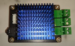
Solve- can you share a picture of the other side of the board? I've been wanting to order one, but the vendors don't really know what they're shipping, and your post shows the most up-to-date version apparently. It appears as if the input is now a 3.5 mm Jack? Thanks.
Here you goe.Solve- can you share a picture of the other side of the board? I've been wanting to order one, but the vendors don't really know what they're shipping, and your post shows the most up-to-date version apparently. It appears as if the input is now a 3.5 mm Jack? Thanks.
Attachments
"Easy". Well, if I routinely did the work X does, maybe I'd spend $400 on ebay for just the hot tweezer attachment for my Metcal station...
I've accepted I'm just too clumsy for 603 (1 mm...) SMD rework. I could always ask my wife; she's even 5 years out of practice. I can accidentally burn plastic bodied components and wire jackets working on point to point tube amp wiring! That's what's easy to do for me.
I've accepted I'm just too clumsy for 603 (1 mm...) SMD rework. I could always ask my wife; she's even 5 years out of practice. I can accidentally burn plastic bodied components and wire jackets working on point to point tube amp wiring! That's what's easy to do for me.
One of those $50 hot air pencils, $20 Swiss made tweezers, $15 binocular magnifier goggles. Those are the three important tools. Over the last 10 years my eyes have gotten worse and I cannot do anything without magnifiers. But it’s not expensive to do SMT. Add an old kitchen fry pan or skillet and a $10 hot plate.
I can relate to that. I have the hot air pencil and tweezers, but I'm afraid I'll heat all the components on 1/2 the board up to solder melt just trying to move the one part. Perhaps I should practice on some SMD build I dont care about, to get good at it?Over the last 10 years my eyes have gotten worse and I cannot do anything without magnifiers.
- Home
- Amplifiers
- Class D
- Infineon MA12070 Class D