I'm pretty anxious to order the pcb's but as it seems now nothing major will be changed. I'm very greatful to Walter (and Anders too I'll hope) that he is very dedicated so the rest of you can get a good design. I'm pretty confindent that he will succeed and will 100% satified.... only if he stays cool and work slowly, one type of part at the time.
I'm also bit surprised that noone are willing to sacrifice anything, not contribute with anything, not even if they get paid but as long as a couple of prototypes are built it's enough I think. I'm pretty sure of the design and I'll expect that it will work OK.
I'm also bit surprised that noone are willing to sacrifice anything, not contribute with anything, not even if they get paid but as long as a couple of prototypes are built it's enough I think. I'm pretty sure of the design and I'll expect that it will work OK.
Hi P-A
My comments at this point in time.
To populate the board is not something that should scare people of. I myself am not at all experienced in soldering SMD stuff but when you work slow and thorough it's not all that difficult. If you have a magnifying glass on a stand and a good pair of tweezers, not those crappy plastic ones, everything goes pretty well. I'm not using the double solder iron method as you once proposed.
The only thing that possible future builders can see as a potential problem is the availability of some components. By this I refer to the op-amp and voltage regulators. Maybe there is an option to include these parts in the order.
Cheers
Walter
When to finish?
Hi P-A!
I have done all the SMD-work exept for the op-amp. I have not heard anything from AD yet, but if anybody knows if it's possible to buy the op-amp anywhere I'll do that. I don't want to solder on the rest of the components before I have the op-amp on place.
The only thing i miss exept from the op-amp is the output coil.
Could You send me two of these P-A??
BR AndyB
Hi AndyB,
From Per-Anders' QRP02 pages:
Well, why don't you just take a 1.5mm diameter wire (single core, no litz, preferably 'copper-laquer' or 'transformer winding' wire) and wind 14 turns of it around an 8mm drill shaft or screwdriver?
After all, you're a beta-tester. The 'end users' would have go through that, too. 😉
The tolerance of the coil's inductance should not be of too much importance, so even if you can't measure your winding result, 14 turns around 8mm should be sufficient (according to most literature sources).
Sebastian.
PS: P.-A., have you tried to leave the output filter out? Would be interesting to estimate the end user's probability to achieve stability with selfmade inductors (or even none at all).
The only thing i miss exept from the op-amp is the output coil.
Could You send me two of these P-A?
From Per-Anders' QRP02 pages:
Output filter, 14 turns, diam 8 mm, 1.5 mm wire, 5 mohms, 0.7 uH
Well, why don't you just take a 1.5mm diameter wire (single core, no litz, preferably 'copper-laquer' or 'transformer winding' wire) and wind 14 turns of it around an 8mm drill shaft or screwdriver?
After all, you're a beta-tester.
The 'end users' would have go through that, too. 😉The tolerance of the coil's inductance should not be of too much importance, so even if you can't measure your winding result, 14 turns around 8mm should be sufficient (according to most literature sources).
Sebastian.
PS: P.-A., have you tried to leave the output filter out? Would be interesting to estimate the end user's probability to achieve stability with selfmade inductors (or even none at all).
I have made two inductors for AndyB 🙂
No sek, I haven't investigated the need or "unneed" for the filters. I leave this to be something for builders to find out.
Just for reference:
Length 25 mm.
8 mm, 1.3 mm wire, 17 turns = 1.0 uH
10 mm, 1.3 mm wire, 17 turns = 1.4 uH
8 mm, 1.5 mm wire, 14 turns = 0.7 uH
10 mm, 1.5 mm wire, 14 turns = 1.0 uH
As you see it's not particulary sensitive how you make your inductor. Somewhere between 0.7 and 1.4 uH is normal think.
It's pretty easy to wound yourself. You just have to have something round, long arms 🙂 and a straight wire. I have praticed winding coils so I have technique but it's pretty heavy work.
PS: You have to translate the wire diameter to AWG yourself (how do you measure AWG really, a really weird way of measuring , could be brittish
  , even the brittish has gone over to mm, can't you amercans also do that?)
No sek, I haven't investigated the need or "unneed" for the filters. I leave this to be something for builders to find out.
Just for reference:
Length 25 mm.
8 mm, 1.3 mm wire, 17 turns = 1.0 uH
10 mm, 1.3 mm wire, 17 turns = 1.4 uH
8 mm, 1.5 mm wire, 14 turns = 0.7 uH
10 mm, 1.5 mm wire, 14 turns = 1.0 uH
As you see it's not particulary sensitive how you make your inductor. Somewhere between 0.7 and 1.4 uH is normal think.
It's pretty easy to wound yourself. You just have to have something round, long arms 🙂 and a straight wire. I have praticed winding coils so I have technique but it's pretty heavy work.
PS: You have to translate the wire diameter to AWG yourself (how do you measure AWG really, a really weird way of measuring
, could be brittish , even the brittish has gone over to mm, can't you amercans also do that?)It's time to pay now.
Check the end of the wiki page http://www.diyaudio.com/wiki/index.php?page=Sj%F6str%F6m+SMD+Gainclone
Check the end of the wiki page http://www.diyaudio.com/wiki/index.php?page=Sj%F6str%F6m+SMD+Gainclone
Thanks for that hint. 😉
Wasn't that the fraction of an inch, e.g. AWG 1 = 1", AWG 100 = 1/100"? No?
However, all you need is a measurement instrument with a scale in mil... 😀
Sebastian.
peranders said:You have to translate the wire diameter to AWG yourself (how do you measure AWG really, a really weird way of measuring
Wasn't that the fraction of an inch, e.g. AWG 1 = 1", AWG 100 = 1/100"? No?
However, all you need is a measurement instrument with a scale in mil... 😀
Sebastian.
.... and you think it was easy..... have you seen the relationship between numbers and the diameter 
O.K. to be a bit more specific.
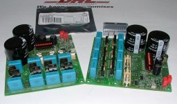
These are all the remaining caps for the amp and the caps for the rectifier part on the board. All I need now are the two transformers and the big power supply caps (4700µF/50V).
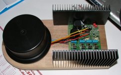
Then a bit more fidling around with the housing and that's it.
Keep you posted.
Cheers
Walter
These are all the remaining caps for the amp and the caps for the rectifier part on the board. All I need now are the two transformers and the big power supply caps (4700µF/50V).
Then a bit more fidling around with the housing and that's it.
Keep you posted.
Cheers
Walter
Attachments

Hi P-A
Didn't knew at the time of ordereing that ELFA was a distributor of Elna cap's. I just used the partnumber code from your sheet to order the parts I couldn't find elsewhere. I now gonna use the TSHA type from Panasonic. The 100µF/50V cap's are also from Panasonic but the FC type.
Cheers
Walter
Didn't knew at the time of ordereing that ELFA was a distributor of Elna cap's. I just used the partnumber code from your sheet to order the parts I couldn't find elsewhere. I now gonna use the TSHA type from Panasonic. The 100µF/50V cap's are also from Panasonic but the FC type.
Cheers
Walter
And guess what......
A few moments ago the transformers and the remaining power supply capacitors were delivered.😀
That means I'm gonna be really busy tonight!
Walter
A few moments ago the transformers and the remaining power supply capacitors were delivered.😀
That means I'm gonna be really busy tonight!
Walter
It's time to pay now. All people on the list have got an email with instructions. If anyone of you doesn't get anything from me in a couple of hours it may have something to do with your spam filters. I have sent the message to myself and BCC'd you all. Some filters think that is spam.
- Status
- Not open for further replies.
- Home
- Group Buys
- Industrial SMD Gainclone - group buy